
- Technology explained – machines and equipment
The exhaust line on a standby generator: from the turbocharger to above the roof
By Tobias Schott · 6-minute read · Updated November 2026
The exhaust line carries the hot exhaust of the diesel engine out of the building. It must be tight, able to expand freely and must not load the turbocharger – otherwise the engine, the building and the people in the room suffer.
A standby generator in a data center often stands in the middle of the building. Its exhaust still has to get outside safely. In between there are pipes, silencers, sometimes an SCR catalyst, plus wall or roof penetrations.
Here we explain how an exhaust line is built, what matters at the turbocharger, how the line passes through wall and roof and what counts for inspection and maintenance.
What is the exhaust line?
The exhaust line is the path of the exhaust from the engine to the open air. Specialists also call it the exhaust system. It starts at the exhaust manifold and the turbocharger and ends at the outlet, usually above the roof.
In between sit components with their own tasks: expansion joints absorb movement, the silencer reduces noise, a catalyst cleans the exhaust. The line itself consists of welded or flanged steel pipes with insulation.
The intake side of the engine is not part of it. That is where the air filter sits with the turbo silencer, the silencer on the air side.
Key facts
- Task: Carry the exhaust safely out of the building.
- Trend: Turbocharger, expansion joint, silencer, catalyst if fitted, penetration, outlet.
- Loading: Heat, thermal expansion, vibration, condensate.
- Key parts: Pipes, flanges, expansion joints, supports, insulation, condensate drain.
- Limit: Exhaust back pressure as specified by the engine manufacturer.
- Interfaces: Manufacturer, designer, fire protection, structural engineering, permit.
- Our part: Rigging in, installation, supports, alignment, maintenance access.
The path of the exhaust
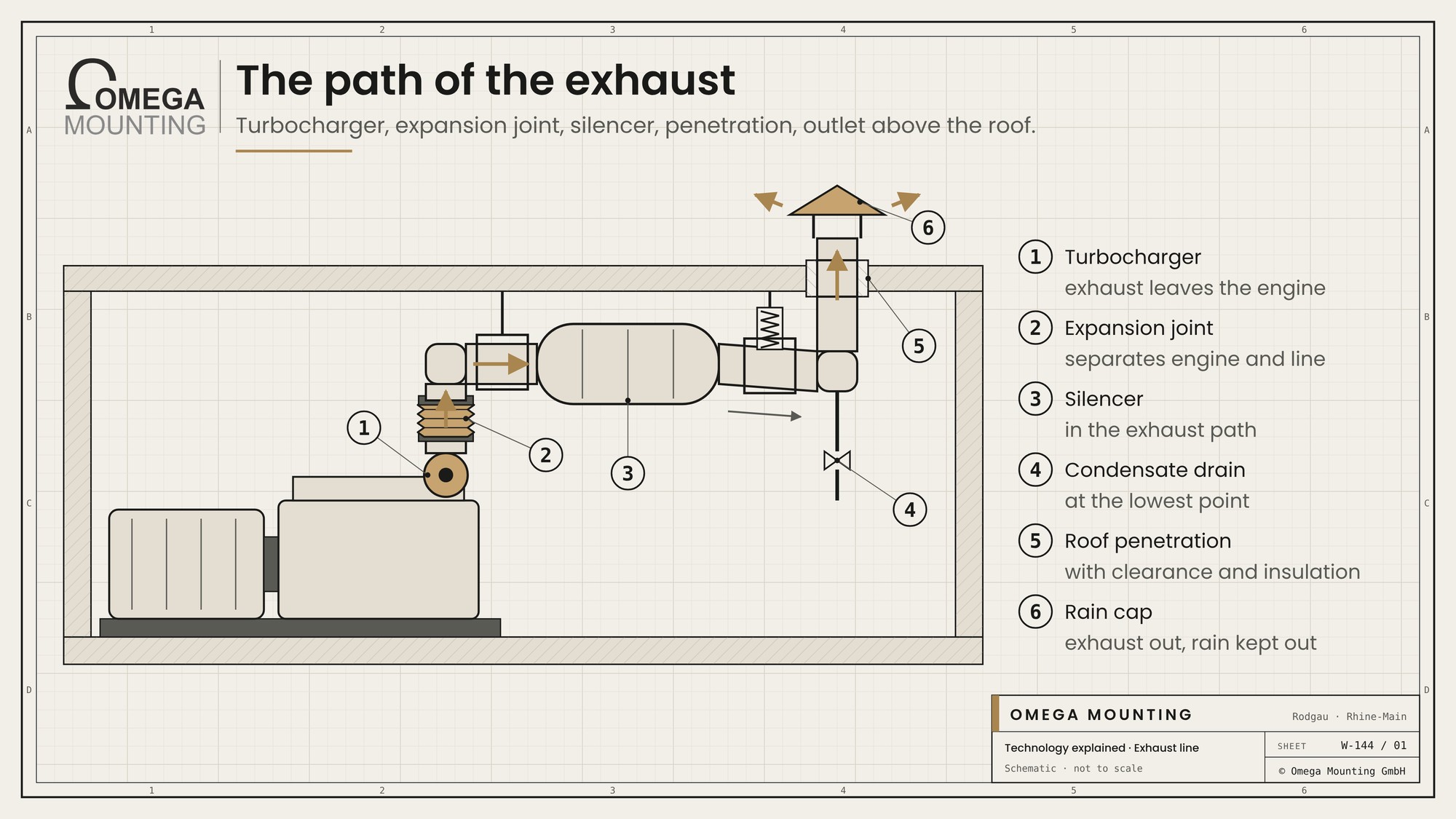
A typical exhaust line in a building has these stations:
- Turbocharger and manifold: This is where the exhaust leaves the engine.
- Expansion joint: A flexible bellows separates the vibrating engine from the fixed line.
- Silencer: It dampens the deep rumble of the exhaust. On plants with exhaust aftertreatment an SCR catalyst sits in front of or behind it.
- Line in the room: Horizontal runs are laid with a slight fall so that condensate drains away.
- Penetration: Through wall or ceiling with a sleeve pipe, clearance and insulation.
- Outlet: A riser leads above the roof. At the top a rain cap or a flap keeps rain from running into the line.
A condensate drain sits at the lowest point. During a cold start water condenses out of the exhaust. It should not run back to the turbocharger.
The longer and more convoluted the line, the higher the exhaust back pressure. This is the resistance against which the engine has to push the exhaust out. If it is too high, the engine loses power and runs hotter. The permissible value is in the manufacturer's documents.
The connection at the turbocharger
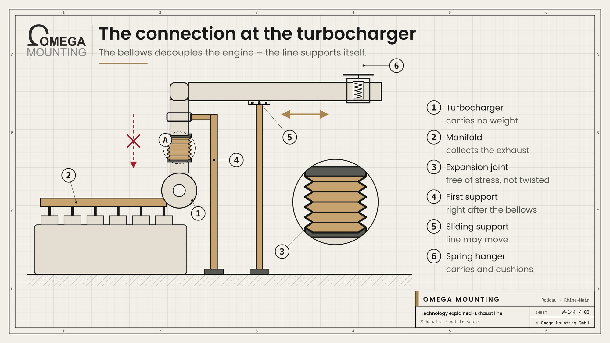
The most sensitive point of the whole line is the connection at the engine. The turbocharger is a fast-spinning precision part. Its exhaust flange is not built to take weight or forces from the line.
| Component | Task | What matters |
|---|---|---|
| Manifold | Collects the exhaust from the cylinders. | Tight flanges, matching gaskets. |
| Expansion joint | Separates engine and line. | Installed free of stress, not twisted. |
| First support | Carries the line directly after the bellows. | Separate support, not on the engine. |
| Fixed point | Holds the line in place at one point. | Set according to the plan, fixed with adequate load capacity. |
| Plain bearing | Lets the line move lengthwise. | Free to move, not rusted solid. |
| Spring hanger | Carries weight and allows movement. | Correctly adjusted, not blocked. |
The expansion joint is not a fix for poor alignment. If it is compressed, stretched or twisted during installation, it tears sooner. That is why we align the line first and only then fit the bellows free of stress.
Many large engines have two turbochargers and therefore two exhaust lines. They are supported individually and only joined behind the expansion joints.
Through wall and roof
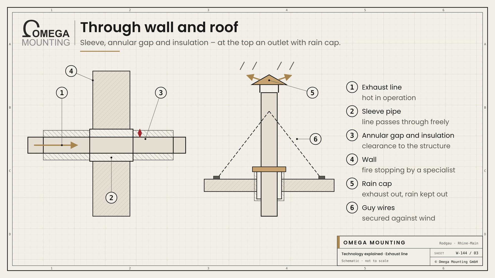
The exhaust line gets very hot in operation. Where it passes through a building element, it needs clearance and protection.
- Sleeve pipe: The line runs through the wall or ceiling in a larger pipe. The annular gap allows for expansion.
- Insulation: It keeps the heat away from the building element and protects people from hot surfaces.
- Fire protection: Penetrations through fire walls need an approved design. A specialist fire protection company plans and builds it.
- Outlet: Height and position of the outlet are set by the designers and the permit so that exhaust is not drawn into supply air or windows. We do not give legal advice on this.
- Rain cap: It lets exhaust out and keeps rain out. Flaps must stay free-moving.
On the roof, wind and weather come into play. Risers are secured against wind with guy wires or fixed to a frame. The structural engineer clarifies the loads.
Installation and rigging in
Exhaust lines consist of large, heavy parts. In data centers they often have to go through narrow plant rooms, via shafts or onto the roof by crane.
We plan the sequence so that heavy parts such as silencers are placed first and the pipes are fitted afterwards. Long runs are installed in sections, each section supported immediately. Temporary hangers carry the parts until the final supports are in place.
Flanges are tightened with new gaskets and in a crosswise pattern. Welded joints need a hot work permit and a fire watch. The insulation only goes on once all joints have been checked.
Inspecting and servicing

The exhaust system is part of the inspection scope at every maintenance of the standby power system. The main checks are:
- Flanges: Soot traces at joints indicate leaks.
- Expansion joints: Cracks, deformation, discolouration on the bellows.
- Supports: Sliding supports free, spring hangers not blocked, bolts tight.
- Insulation: damaged or wet areas.
- Condensate drain: clear and tight.
- Outlet: Rain cap and flap move freely, no bird nests.
Leaks often only show under load. That is why a test run with real load, for example via a load bank, is part of the inspection. The exhaust back pressure can also be measured at a test point. The measurement and its assessment are carried out by the manufacturer or its service team.
Typical mistakes
Many failures of exhaust lines originate during installation.
A classic is the missing support directly behind the expansion joint. The weight of the line then hangs on the bellows and the turbocharger. The bellows tears and the turbocharger wears faster. A second mistake is blocked sliding supports: the line cannot expand and presses on supports and penetrations.
Missing or wrong fall is also common. Condensate collects in low spots, attacks the pipe from the inside and in the worst case runs to the engine. And finally insulation applied too early: it hides leaking flanges that only show up during the test run.
All these mistakes can be avoided if the line is built in the right sequence and tested under load before insulating.
What we pay attention to
When rigging in and installing exhaust lines, we pay attention to points that become expensive later.
- The turbocharger carries no weight of the line.
- Expansion joints sit free of stress and untwisted.
- Fixed points, sliding supports and spring hangers sit according to the plan and stay movable.
- Horizontal runs fall towards the condensate drain.
- Access for inspecting and replacing bellows, insulation and drain stays free.
- Design, back pressure and commissioning are the manufacturer's responsibility.
Where we use it
During the rigging in standby generators in data centers in the Frankfurt area the indoor solution included not only the radiator and SCR system but also the manifold and exhaust line. Commissioning was done by the manufacturer. During the generator overhaul of a backup power system the exhaust system is one of the areas kept in view during maintenance. More about our services is on the page energy and standby power.
More technology explained
Technology explained
how urea reduces nitrogen oxides.
Technology explained
intake side, exhaust and cooling air.
Guide
our guide to maintenance, repair and replacement.
Do you have questions about how this works on your site?
Are you planning an exhaust line in a data center or need to replace an existing one? We rig in, install and coordinate with the manufacturer. Request a callback.
Free, no-obligation callback
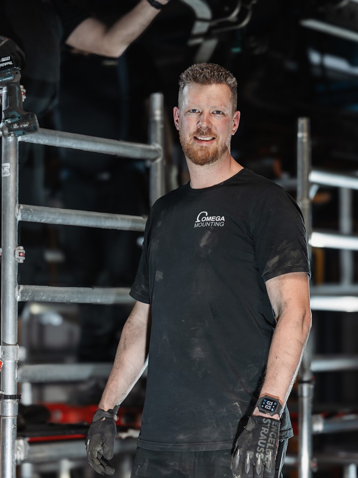
About the author
Tobias Schott
Managing director of Omega Mounting GmbH, Rodgau · more than 20 years of hands-on experience in installation and maintenance
A trained mechatronics technician, working in maintenance, servicing and industrial installation since 2004 – first alongside his father, and with Omega Mounting since 2012: from overhead conveyors in Frankfurt to the crane system in a new-build hall. He plans and leads lifting operations as an appointed person (AP) in data centers and on industrial sites in the Rhine-Main region, trains and examines operators of cranes, mobile elevating work platforms and telehandlers, and is a qualified occupational safety specialist. On jobs abroad he is known as the “German Troubleshooter” – the person you call when a site gets stuck. He learned what quality means from his father, not from a manual: Made in Germany as a standard for his own work, not a label. That is why quality comes first at Omega Mounting – ahead of speed and price. The Technology explained articles cover the equipment and techniques his team uses every day: what counts on site is in them – what only appears in the brochure is not.
 English
 German