
- Guide – Lift & Shift
Planning a moving-in operation: floor loads, openings and crane set-up areas
By Tobias Schott · Reading time approx. 24 minutes · Last updated: October 2026
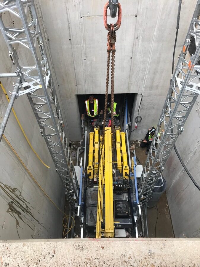
A piece of equipment that comes into a building must one day come out again. Anyone who defines installation opening, floor load, transport route and crane set-up area at the design stage saves core drilling, structural surveys and change orders on the installation day.
You are designing a plant building, a production hall or a data center, and somewhere on your list it says: standby generator, transformer, chiller, machine tool, automated storage unit. The data sheets are available, the installation area is drawn in. But how does the machine get there? Anyone planning moving in has to think about floor load, opening, route and equipment together – and answer the question of how the unit will come out again in fifteen years.
This question is often asked too late in the design. Then, on the installation day, an installation crew stands in front of a door opening that is three centimetres too narrow. Or in front of a floor whose payload nobody knows, or in front of a crane set-up area with a duct underneath. That costs time, money and nerves – and sometimes a wall. Anyone searching for “planning moving in floor load” wants to avoid exactly that.
This article shows designers what they should plan for moving in: floor load and load distribution, installation and assembly openings, moving-in routes with door openings and turning radii, crane set-up areas and access routes, replaceability and reserve areas. With examples from Raunheim, Frankfurt and the Rhine-Main region in which the planning was good – or in which we had to find a route afterwards.
Key points at a glance
- Moving-in planning is part of building design: openings, floor loads, transport routes and crane set-up areas are defined in the design, not improvised on the installation day.
- Every unit needs a defined route in and out – via a gate, a removable facade panel, a roof opening or an installation shaft.
- Floor loads must be checked for the transport state, not just for the installed state: machine skates and heavy-duty skates generate point loads that the structural engineer has to assess.
- Moving-in routes are dimensioned at their narrowest point – door opening, clear height, turning radius, lift car – with reserve for packaging, skates and lifting accessories.
- Crane set-up areas need load-bearing ground without shafts and ducts, an access route with a suitable swept path for heavy haulage and a place in the construction sequence.
- Replaceability means: the moving-in route remains clear over the service life or can be reopened with reasonable effort.
- The earlier an installation contractor checks the design, the cheaper every correction is – ideally in the design phase, at the latest before tendering.
What is moving-in planning?
Moving-in planning is the systematic definition of the route, the equipment and the structural conditions by which a heavy or bulky unit gets into a building. It also defines how the unit comes out again for maintenance or replacement.
It links three disciplines: architecture (installation openings, moving-in routes, door openings), structural engineering (floor loads, load assumptions, crane set-up areas, load distribution) and installation technology (lifting method, heavy-duty skates, lifting accessories, lift plan). The lift plan is the document in which the installation contractor later records weight, centre of gravity, lifting points, lifting equipment with radius and hook height, and the load path of every single lift. It can only be as good as the planning on which it is based.
The term lift & shift describes the service that stands at the end of moving-in planning: lifting, moving and positioning heavy equipment inside the building. What an installation contractor does in the process is described on our page Lift & shift – moving in heavy equipment. This article is about what has to be done beforehand.
Which installation openings should you provide – gate, facade, roof or shaft?

For every heavy unit, you should provide an installation opening that is larger than the largest component in its transport state. Whether gate, removable facade panel, roof opening or installation shaft depends on the location of the installation site, the building height and how often the opening will be needed.
| Type of opening | Suitable for | Advantages | Points to note |
|---|---|---|---|
| Installation gate on the ground floor. | Plant rooms at ground level, production halls. | Usable at any time, no crane needed inside the building. | Gate opening sized to the largest component plus heavy-duty skates. Threshold and ramp. Traffic route in front. |
| Removable facade panel. | Plant floors on upper storeys, later replacement. | Stays closed in normal operation, no permanent gap. | Fixing and sealing designed for repeated removal. Crane set-up area in front of the facade. Fall protection at the fall edge when the panel is open. |
| Roof opening / assembly opening in the roof. | Rooftop plant rooms, chillers, units on the roof. | Direct crane lift from above, short routes. | Hook height, radius and slewing range of the crane. Roof penetration and sealing. Load transfer of the roof structure during the lift. |
| Installation shaft. | Basement and lower-ground plant, multi-storey plant areas. | One route for all levels, reusable later. | Shaft dimension with reserve. Cover load-bearing and removable. Hook height for lifting over the shaft edge plus height of the chain sling. Keep the shaft clear. |
The shaft that was built in
An example of what happens when the moving-in route is not kept clear. In a data center in Raunheim, a spider crane – a compact mini crane on crawler tracks – had been brought into the basement during the shell construction phase to install air-conditioning units there. When it was due to come out again, the building had been completed around it: partition walls, fittings and a construction hoist in the retrieval shaft that could not be moved. At the site survey, two centimetres were missing for the upright lift. How the lift succeeded anyway is described in the practice section. The lesson for the design: a shaft is a permanent moving-in route, not a construction state.
Assembly openings as a reserve
Not every opening has to stay open. Well planned is an assembly opening that is closed in normal operation: as a bolted facade panel, as a non-load-bearing wall with a defined breakout or as a roof section with removable covering. In the structural design it is provided so that it can be reopened without a structural survey and without intervening in load-bearing parts. Document this opening like an inspection opening in the as-built drawings and records; in fifteen years someone will be looking for it.
How do you plan floor loads and load distribution for moving in?
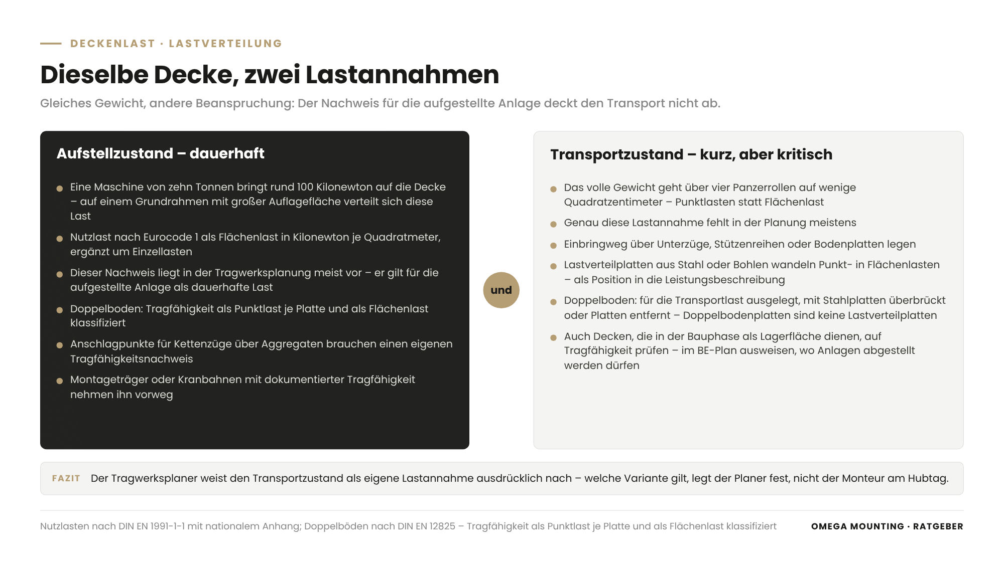
Floor loads must be verified for two states: for the installed unit as a permanent load and for the transport state. In the transport state, the full weight goes into the floor as point loads through a few machine skates or heavy-duty skates. This second load assumption is the one most often missing from the design.
Planning floor load for moving in: distributed load, point load, transport load
Floor slabs are designed in accordance with DIN EN 1991-1-1 (Eurocode 1) for imposed loads specified as a distributed load in kilonewtons per square metre. Concentrated loads are applied in addition. A machine of ten tonnes puts around 100 kilonewtons onto the floor. If it stands on a base frame with a large bearing area, this load is distributed. If it rolls on four machine skates – compact heavy-duty skates with small steel or polyamide rollers – the same load is concentrated on four areas of a few square centimetres. That is a different stress, even though the weight stays the same.
The consequence for the design: route the moving-in route over floor areas with high load-bearing capacity – over downstand beams, rows of columns or ground slabs. Have the structural engineer explicitly verify the transport state as a separate load assumption. Where that is not enough, load spreading plates made of steel or planks are used to convert the point loads into distributed loads. That costs time on the installation day and therefore belongs in the specification as an item.
The same check applies to floors on which material or plant components are stored temporarily during the construction phase. The BG BAU/BAuA module “Site set-up – traffic areas, transport routes, storage and set-up areas” requires every floor slab used as a storage area to be checked for its load-bearing capacity. For you as a designer this means: show in the site set-up plan where equipment may be parked before moving in – and where not.
Special case: raised floor
In data centers and control rooms, the equipment sits on raised floors in accordance with DIN EN 12825 – elevated panel systems on pedestals, whose load-bearing capacity is classified as a point load per panel and as a distributed load. There are three ways to transport heavy equipment over the raised floor. Either it is designed for the transport load. Or the route is bridged with load spreading plates or a roadway of steel plates. Or the panels are removed along the route and the load is moved on the subfloor. Which variant applies must be defined by the designer – not by the fitter on the lift day. One rule from our own practice: raised floor panels are not load spreading plates. Under heavy-duty skates and crane outriggers we only ever place plates intended for the purpose – even when the site is in a hurry.
Floor loads at lifting points
It is not only the floor that bears the load. If a chain hoist is needed on the ceiling or on a beam structure in the plant room, the lifting point needs a load-bearing verification. When removing the generator of a standby power system – a standby generator set – in a larger building complex, we lifted the generator using several chain hoists on a beam structure. It was then separated from the engine and set down on machine skates. Assessing the load-bearing capacity of the lifting points was part of the planning before the working day. Designers can anticipate this verification by providing assembly beams or crane runways with documented load-bearing capacity above generator sets and large machines.
What dimensions do transport routes need: door widths, heights, turning radii, lifts?
A transport route is dimensioned at its narrowest point. The largest component in its transport state – with packaging, heavy-duty skates and lifting accessories – must fit through every door opening, under every downstand beam, around every corner and into every lift that the route touches.
The four dimensions you have to check
- Clear width of every door, every passage and every corridor – the door opening including frames, door leaves, services, fire dampers and pipes that project into the cross-section.
- Clear height – not the room height, but the lowest dimension under downstand beams, cable trays, ventilation ducts, sprinkler pipes and luminaires. Add to this the height of the skates under the load.
- Turning radius – a long component needs more space than its width at every corner; the swept path of the load must fit into the corridor. Rule of thumb: every 90-degree corner is a check dimension in its own right.
- Lifts – lift capacity, car dimensions, door opening and the payload of the lift lobby. A goods lift that can carry the machine is no use if the machine does not fit into the car.
When the building was never intended for it
During the relocation of six automated storage units – vertical carousel storage lifts – from an office high-rise in Frankfurt to Rodgau, the building had never been designed for such equipment. Doors and passages were too low for transport in one piece, and the use of machinery was out of the question. Three pinch points determined the dismantling plan. What follows from this for the designer: anyone who plans equipment into a building that was not built for it plans for dismantlability – or for the opening.
Plan for reserve
There has to be air between component and opening. How much depends on the lifting method: a load on the crane hook swings, a load on machine skates needs space for steering, a load in a hydraulic gantry needs space for the gantry legs. A gap of a centimetre, as in the spider crane retrieval in Raunheim, is feasible, but requires banksmen on every side and costs time. In the design, every reserve is cheaper than on the installation day.
How do you dimension crane set-up areas and access routes?
A crane set-up area must absorb the crane's outrigger forces without settlement. It must be free of shafts, ducts and areas with basements beneath them, or be supported accordingly. And it must be reachable by heavy haulage and actually be available in the construction sequence at the time of moving in.
Outrigger forces and ground bearing pressure
A mobile crane rests on four outriggers. The outrigger force per outrigger depends on crane, configuration, counterweight, load and radius and can be a multiple of the load being lifted. The crane company supplies the outrigger forces for the planned lift from the load chart. The structural engineer assesses whether the ground – natural ground, base course, underground car park slab, yard paving – can bear them. Outrigger pads under the outriggers increase the bearing area and reduce the ground bearing pressure. The BG BAU/BAuA module “Site set-up – large equipment” describes how the outrigger force spreads through the ground at an angle of about 45 degrees. A look at the surface is therefore not enough; what lies beneath counts. The German technical rule TRBS 2111 Part 1 (mobile work equipment) names pads for load distribution and load distribution plans as protective measures. It requires that the crane operator is briefed on the load-bearing capacity of the ground. For you this means: whoever knows the load-bearing capacity must pass it on – in figures, not as a promise. What must be defined in the design: where may the crane stand, what ground bearing pressure is permissible, how large is the slewing range, and which underground structures are off limits?
Shafts, ducts, pipes
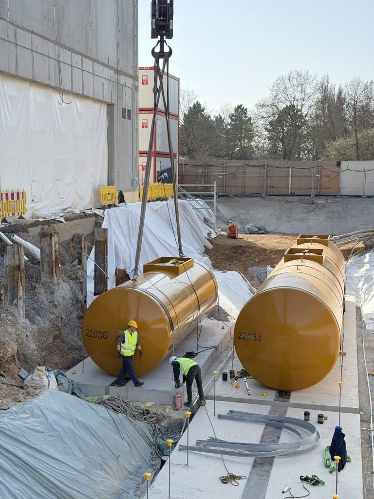
The most common surprise on the installation day is what lies beneath the set-up area: ducts, cable shafts, cisterns, basement rooms, light wells. In the placement of five 100-cubic-metre diesel tanks into the pit of a data center in Raunheim shafts, ducts and basement shafts lay beneath the routes around the building. The standing areas for the crane were limited. The permissible crane set-up areas were determined from a survey of areas and ground and calculated in CAD. The choice of crane followed the required radius and the load moment. In the end, the mobile crane worked with a 52-metre main boom and a radius of up to 44 metres, because it could only stand in a few places.
If the crane stands next to an open pit, as it did there, a further distance comes into play. The “large equipment” module specifies safety distances between cranes and sloped excavations in accordance with DIN 4124. These are at least 1.00 metre for machines up to 12 tonnes total weight and at least 2.00 metres between 12 and 40 tonnes. For non-cohesive or filled ground, twice the pit depth applies. A mobile crane for a moving-in job with counterweight is usually well above these weight classes, so the structural design of the shoring or the slope determines the distance. For the designer this means: a crane set-up area at the edge of the pit only becomes a set-up area once the structural engineer has approved the distance.
Access and heavy haulage
Each tank came individually as an abnormal load through a residential street with trees and pavements. Whether a low-loader with a tank a good 16 metres long could even get from the road onto the site was checked in advance with a swept path calculation. The gate systems had to be removed before the crane arrived. Abnormal loads need a permit under Section 29(3) of the German Road Traffic Regulations (StVO); a crane set-up area in public space needs a special use permit with a traffic order – both take lead time. For the site access itself, the “traffic areas” module gives guide values against which you can measure your design. These are a minimum inner radius of around 5.50 metres for access routes and bends and 3.0 to 3.5 metres width for a single-lane site road. Add to this a clearance profile of at least 4.50 metres height. For heavy haulage with a tank or transformer these are lower limits, not target values. For the designer this means: access width, swept paths, clearance heights, gates, kerbs and tree locations are part of moving-in planning – not just the building itself.
The set-up area in the construction sequence
A crane set-up area is an area at the right time. In Raunheim, the area behind the pit was the crane set-up area – and later became the tank area itself, so it had to be cleared between lifts. On tightly built-up plots in Frankfurt, Offenbach or Mainz, this is the rule: the set-up area competes with storage areas, site set-up, site roads and later external works. Plan it into the construction schedule and the site set-up plan like a trade.
Why you should plan for replaceability from the outset
Replaceability means that every unit can be removed and replaced with reasonable effort over its service life. This presupposes that moving-in route, opening, crane set-up area and floor load are documented and kept clear not just for the initial installation but for replacement.
Technical equipment has a shorter life than buildings. Standby generators, chillers, transformers, air-conditioning units and machine tools are replaced at least once in a building's life cycle, often several times – and partially dismantled for overhauls in between. With the generator of the standby power system that we describe in the practice section, the dismantling of the enclosure and the coupling assembly had been underestimated in the preliminary planning. The fact that the removal was possible at all was because the installation shaft existed and was clear.
Three questions you as a designer should answer for every large unit:
- How does the unit come out in fifteen years? The same moving-in route as it went in – or will that be built in, built over, occupied as a storage area by then?
- What has to be dismantled for this? Enclosures, silencers, pipework, cable trays, partition walls – and is this noted in the as-built drawings and records?
- Where does the crane stand? Is the crane set-up area still a reserve area by then – or a car park, landscaping, an extension?
Especially in the data center, where chillers, air-conditioning units and generators are replaced during ongoing operations, the moving-in planning of the new build decides how laborious every later replacement will be. Read more on our page Installation and lift & shift in data center construction.
Which reserves belong in every moving-in plan?

Every moving-in plan needs reserves for packaging and transport frame, for heavy-duty skates and lifting accessories, and for tolerances between data sheet and reality. Add to this the reserve for the case that the next equipment generation is larger than today's.
Packaging and transport frame
A machine rarely arrives bare. It stands on a pallet, in a wooden crate, on a transport frame or a base frame bolted on for transport. For the generator removal we made custom transport frames of timber and steel for the heavy assemblies; in the PDC project the cabinets stood in wooden crates. The transport dimensions are therefore larger than the installation dimensions – and both are in the data sheet if you ask for them.
Skates and lifting gear
Under the load are the skates, above the load hang the slings. Both need space: machine skates and heavy-duty skates a few centimetres under the load, a chain sling or a spreader beam with round slings quickly one to two metres above it, depending on the sling angle of the legs. Anyone planning a hook height adds the sling height. Anyone planning a clear height adds the skates.
Tolerance between data sheet and reality
Weights in data sheets are often nominal or dry weights; operating fluids, accessories, options and packaging are added. Dimensions apply to the standard configuration. For moving-in planning, request the transport data: transport weight, transport dimensions, centre of gravity, lifting points, permissible transport orientation. Whatever the manufacturer does not supply, the installation contractor determines during the site survey – before the installation day, not during it.
The next generation
Equipment usually becomes more compact for the same output, or more powerful for the same size – but not always. Anyone who plans a reserve of one equipment size into openings and routes is on the safe side when replacing in fifteen years.
When should you bring the installation contractor into the planning?

You should involve the installation contractor in the design phase, when openings, routes and set-up areas can still be moved. At the latest, however, before tendering, so that moving in and client-provided works are unambiguously described and no change orders arise.
| Design phase | What the installation contractor contributes | What you provide for it |
|---|---|---|
| Design. | Plausibility check of installation openings, moving-in routes, crane set-up areas. Advice on lifting methods (mobile crane, spider crane, hydraulic gantry, skidding system) and their space requirements. | Floor plans, sections, equipment list with rough weights. |
| Detailed design. | Transport route study per unit. Load assumptions for the transport state to the structural engineer. Requirements for assembly openings, installation sequence. | Manufacturer data (transport weight, dimensions, centre of gravity), floor plans, external works plan. |
| Tender. | Description of the moving-in service. Interface list for client-provided works (openings, load distribution, crane set-up area, closures). Time window. | Scope of works, construction schedule, site set-up plan. |
| Before the installation day. | Site visit, site survey, lift plan. Coordination with crane company and trades. | Access, contact persons, lift clearance. |
Experience shows: every correction that costs a line in the design costs a meeting in the detailed design, a change order in the tender and a core drill on the installation day. Our site visit before projects in Offenbach, Darmstadt or Mainz therefore begins with the question to the designer: which opening is intended for moving in – and who last saw it?
How we do it in practice
Our projects show both sides of moving-in planning – buildings in which the route was provided, and buildings in which we had to find it afterwards.
Spider crane from the basement of a data center in Raunheim
With the retrieval of a spider crane from the basement of a data center in Raunheim the building had been completed around the machine. Four fitters, one day. First, the complete route through the basement was measured – every door opening, every corner, every obstacle. Because diesel operation was not possible in the data center, the crane ran electrically on a long three-phase cable. Through the basement it went with one driver and a banksman on each side. In the retrieval shaft stood a construction hoist that could not be moved. Hoist and ramp were packed with timber baulks to distribute the load. For the lift with the tower crane there was a lift plan with lifting points, geometry, sequence and responsibilities. Because two centimetres were missing upright, the crane hung at a controlled angle on a four-leg, shortenable chain sling.
Six automated storage units from a Frankfurt high-rise to Rodgau
During the relocation of six automated storage units from an office high-rise in Frankfurt to a hall in Rodgau the narrowest passages determined the entire process. The units just fitted under the ceiling, three interior doors were too low, the floor was parquet worth protecting, and the use of machinery was out of the question. So every unit was documented, labelled and photographed before dismantling. It was then dismantled into individual parts that fitted through the narrowest passage, moved on dollies over the parquet and loaded into containers – with six fitters for loading. In Rodgau the units were reassembled, mechanically aligned and commissioned together with the equipment manufacturer. How we plan such relocations is shown on our page machinery relocation in the Rhine-Main region.
Generator of a standby power system through the installation shaft
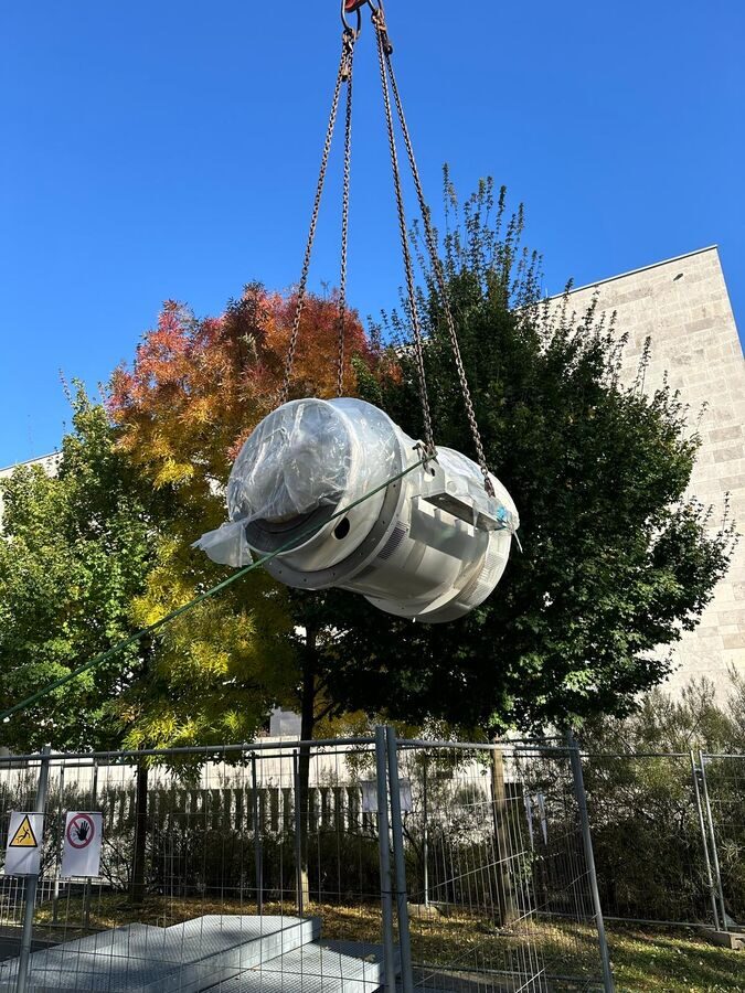
During the removal and reinstallation of the generator of a standby power system by mobile crane the plant room lay deep inside a building complex in the Rhine-Main region. The enclosure was dismantled, the generator slung on several chain hoists on a beam structure, lifted, separated step by step from the engine and set down above the base frame. After removing the coupling assembly, it went on machine skates through narrow building corridors to the installation shaft. There the mobile crane lifted the assembly vertically upwards. An appointed person for lifting operations coordinated, three mechanics worked. What had to be planned in advance: check door openings, select lifting accessories, size lifting equipment, assess the load-bearing capacity of the lifting points, make transport frames. The installation shaft was the route the designer had provided years earlier – and it worked.
Are you facing a comparable moving-in job – whether in the design or in a building that was never intended for it? Then get in touch with us: a site visit with floor plan and equipment list usually settles within an hour which route and which lifting method fit.
What this means for your role
For buyers: Award the moving in to a contractor who checks the design before submitting a quotation. Site visit, transport route study and lift plan belong in the scope of works as items, not as optional items. Include openings, load distribution and crane set-up area in the interface list so that “by the client” and installation service are cleanly separated. A quotation without this basis is an estimate, not a price – and the change order is pre-programmed.
For designers: Include moving in as a design subject in its own right in the design and detailed design. This includes one installation opening per large unit and a verified moving-in route with door openings, clear heights and floor load in the transport state as a separate load assumption. Add to this a crane set-up area with ground bearing pressure, radius and slewing range, reserve areas and a note on replaceability in the as-built drawings. Request transport data with centre of gravity and lifting points from the manufacturer, not just installation data.
For project managers and site managers: Before tendering, check whether moving in and client-provided works are unambiguously assigned in the interface list. By the client are usually: creating and closing assembly openings, load spreading plates, crane set-up area, barriers, special use permit and traffic order. Unclear interfaces are the most common cause of change orders in moving in. Reserve the crane set-up area in the construction schedule and the site set-up plan, keep the moving-in route clear of preceding trades until the installation day (a clear work area) and define who issues the lift clearance.
For maintenance managers: You are the one who will need the moving-in route again in fifteen years – for inspection, for repair in the existing plant or for replacing the unit at the end of its wear reserve. Record installation openings, shafts and crane set-up areas in your as-built documents and records and make sure they do not gradually turn into storage areas or service routes. If a design today manages without a replacement route, you are the voice that asks about it – because later you are responsible for the maintenance window in which the replacement has to fit.
Designer's moving-in checklist on request: floor loads, openings, routes, crane set-up areas
Our designer's moving-in checklist is a two-page working aid that organises the check points of this article by design phase. In the design, these are openings, routes and set-up areas. In the detailed design follow floor loads in the transport state, raised floor, suspension points and assembly openings; in the tender, interfaces, client-provided works and time windows. Add to this a query list for manufacturer data (transport weight, dimensions, centre of gravity, lifting points) and the three questions on replaceability. It answers the questions behind “planning moving in floor load” point by point and helps designers draw up the plans, project managers clarify the interfaces and buyers formulate the specification. Request the designer's moving-in checklist via our Contact form – keyword “Designer's moving-in checklist”.
Why Omega Mounting?
We are based in Rodgau near Frankfurt and move heavy equipment into data centers, production halls and plant buildings throughout the Rhine-Main region. From Raunheim via Frankfurt and Offenbach to Hanau, Darmstadt and Mainz. The linked projects show that we not only use moving-in routes but measure them, calculate them and, if necessary, find new ones. Our own workshop in Rodgau manufactures transport frames, auxiliary structures and load distribution when standard solutions do not fit. Via our 24-hour hotline you can reach us even when a moving-in job has to be replanned at short notice. Designers prefer to involve us early – because an hour at the drawing is cheaper than a day at the wall. What you get from us: a single point of contact from the plausibility check in the design to the lift plan on the installation day. Plus lifting technology, installation and transport frames from a single source and short distances to every site in the Rhine-Main region.
Conclusion
Planning moving in means treating floor load, openings, transport routes and crane set-up areas as part of the building design. This includes verifications for the transport state, reserves for packaging, skates and lifting gear and a documented route for replacement in fifteen years. Anyone who defines this in the design saves structural surveys, core drilling and change orders on the installation day. Anyone who neglects it needs an installation contractor who can still find a route – but that is the more laborious option. If you would like your design checked for moving-in feasibility before the first low-loader rolls: Send us floor plans, sections and the equipment list with weights. We will come back to you with an honest assessment of which opening, which floor and which set-up area will carry the load.
Planning maintenance, moving in or installation in the Rhine-Main region?
Tell us briefly what it is about – we will come back to you with an honest assessment.
100% free and without obligation
You may also be interested in these guides

About the author
Tobias Schott
Managing director of Omega Mounting GmbH, Rodgau · more than 20 years of hands-on experience in installation and maintenance
A trained mechatronics technician, at home in maintenance, servicing and industrial installation since 2004 – first at his father's side, since 2012 with Omega Mounting: from the overhead conveyor in Frankfurt to the crane system in a new-build hall. Plans and leads lifting operations as appointed person in data centers and on industrial sites in the Rhine-Main region, is an instructor and examiner for cranes, mobile elevating work platforms and telehandlers, and a safety officer. On jobs abroad he is known as the “German Troubleshooter” – the one you call when things get stuck on site. He learned what quality means not from a manual but from his father: Made in Germany as a standard for his own work, not as a label. That is why it comes first at Omega Mounting – before speed and before price. He writes these guides from that practice: what works on our sites is in them – what only exists in the standard is not.
Frequently asked questions
An installation opening is the structural opening – gate, facade panel, roof opening or shaft – through which a unit gets into a building. It must be larger than the largest component in its transport state, i.e. including packaging, transport frame, skates under the load and lifting gear above the load, plus reserve for steering or swinging. The specific size results from the manufacturer's transport data and the planned lifting method.
No, the imposed load verification alone is not enough – that is the short answer to the search query “planning moving in floor load”. The verification of the imposed load for the installed unit does not cover the transport state, because machine skates and heavy-duty skates concentrate the weight as point loads on a few small areas. The structural engineer should verify the moving-in route with the actual wheel loads as a separate load assumption or prescribe load spreading plates. This also applies to raised floors, underground car park slabs and lifting points for chain hoists.
Define where the crane may stand, what ground bearing pressure the ground under the outrigger pads can absorb and which shafts, ducts and areas with basements beneath them are off limits. The crane company supplies the outrigger forces from radius and load chart, the structural engineer assesses the ground. Check access and swept path for crane and heavy haulage and reserve the area in the construction schedule – it competes with storage areas, site roads and external works.
In data centers in Frankfurt, Raunheim or Offenbach, equipment stands on raised floors, plots are scarce, and equipment is replaced during ongoing operations. Moving-in planning must therefore take account of raised floor loads, transport routes through secured areas, crane set-up areas on tightly built-up plots and the replaceability of every large unit over its service life. Diesel-powered machines inside the building are usually excluded – electric operation and power supply belong in the planning.
Yes, the principles are the same: every unit needs an opening, a verified route, a set-up area and a replacement route. In production halls, gates and overhead cranes are usually present, but floor verifications for mezzanine levels are often missing. In existing buildings – like the Frankfurt office high-rise with the automated storage units – the dismantlability of the unit replaces the missing opening. What matters in every case is that the question is asked before the equipment is selected.
Transport weight (not just operating or dry weight), transport dimensions including packaging or transport frame, centre of gravity, location and load-bearing capacity of the lifting points or lifting eyes, permissible transport orientations and information on dismantlability into assemblies. If this information is missing, the installation contractor has to determine it during the site survey before the installation day.
The executing installation contractor prepares the risk assessment under Section 5 of the ArbSchG (German Occupational Safety Act) and the lift plan and provides the appointed person for lifting operations. Crane operation is subject to DGUV Regulation 52 and the BetrSichV (Industrial Safety Ordinance), slinging to DGUV Rule 100-500. The client or designer is responsible for the structural prerequisites: load-bearing floors, openings secured against falls, suitable crane set-up areas. They are also responsible for the coordination of trades under Section 8 of the ArbSchG or via the health and safety coordinator and the health and safety plan under the BaustellV (Construction Site Ordinance).
Not a figure, but a list: structural surveys under fast-track procedure, core drilling or wall openings with reinstatement, additional load spreading plates, a larger crane because of a larger radius. Add to this a special use permit and traffic order with lead time, waiting times for the installation crew, postponed commissioning and change orders for all of the above. Each of these items would have been a line on the drawing in the design.
Send us three things via our Contact form: the floor plan with the planned moving-in route, the equipment list with transport weights and the desired period. We check the documents, arrange a site visit with site survey if required and come back to you with a written assessment on opening, floor load, lifting method and crane set-up area. Your contact is Tobias Schott – even when the design is still at the draft stage and lines can still be moved.
 English
 German