
- Guide – Data Center
Installing an exhaust line on a standby generator: routing, expansion joints, supports and silencers
By Tobias Schott · 24-minute read · Updated: November 2026
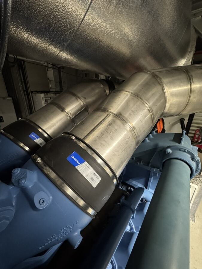
Installing an exhaust line on a standby generator means fitting the manifold, expansion joint, silencer, SCR system where present, pipework and outlet to the manufacturer's and designer's specifications so that the line is tight, can expand freely when hot, puts no weight on the engine and discharges the exhaust gas safely to the open air. The supports are decisive: fixed points and sliding supports determine where the line moves. The expansion joint absorbs movement – but not installation errors.
A standby generator rarely runs. When it does, it runs properly: the engine goes to full load within a short time, the exhaust gas gets very hot, the line grows in length and the engine vibrates on its mounts. That is exactly the moment that shows whether the exhaust line has been installed well. If a flange tears open, a pipe presses against the wall or the silencer hangs on the turbocharger, the test run turns into a building site.
Anyone searching for “installing an exhaust line”, “standby generator exhaust line”, “emergency power exhaust system” or “exhaust expansion joint” is usually facing a new generator set, a replacement or a retrofit. The questions are always similar: how does the heavy silencer get into place? Where are the fixed points? Which way round does the expansion joint go? When is it insulated? And who is responsible for penetrations, fire protection and acceptance?
This guide shows how to have an exhaust line installed on a standby generator – from checking the design through bringing in and setting the components to the test run with a load bank. It is written for operators, technical managers, facility managers, designers, project and site managers, service companies, buyers and occupational safety specialists. How the exhaust line is built in principle is explained in the article The exhaust line on a standby generator. How a complete generator set is replaced is described in the guide Replacing a standby generator.
Key points at a glance
- Installing an exhaust line: Manifold, expansion joint, silencer, SCR system, pipework and outlet form one line that is planned and installed as a whole.
- Vorgaben zuerst. Back pressure, cross-section, outlet and clearances are set by the manufacturer and designer – not on site.
- Heavy parts need a lifting plan. Silencers and SCR systems are brought in like a machine.
- Supports according to plan. Fixed points hold, sliding supports guide, spring hangers carry.
- Expansion joints are not make-up pieces. They absorb movement, not misalignment from installation.
- The engine carries nothing. No weight of the line may rest on the turbocharger or manifold.
- Penetrations with an annular gap. Through fire walls only with an approved design, by a specialist contractor.
- Test first, then insulate. The insulation follows the test run under load.
What is an exhaust line on a standby generator?
The exhaust line carries the exhaust gas of a standby generator from the engine to the open air. It starts at the manifold or turbocharger outlet, runs via an expansion joint to the silencer, on many newer plants through an SCR system for exhaust gas treatment, and ends above the roof or on the façade in an outlet with rain protection.
Specialists also speak of the exhaust system or exhaust run. They mean the same thing: all components through which the exhaust gas flows, together with their supports, penetrations and insulation.
Why the installation is demanding
The line is hot, heavy and moving. It expands when heating up and contracts again when cooling down. At the same time the engine vibrates on its mounts. The installation has to allow both without the line leaking or forces arriving where they do not belong.
New build, replacement or retrofit
In a new build, the exhaust line is planned together with the generator set. In a replacement, the old line often no longer suits the new engine. In a retrofit, an additional silencer or an SCR system is added to an existing line. In all three cases: check the design first, then install.
Where the exhaust line ends
The air filter with a turbo silencer on the intake side is not part of the exhaust line. How this silencer is retrofitted is described in the guide Fitting a silencer to a generator.
Structure: from the manifold to the outlet
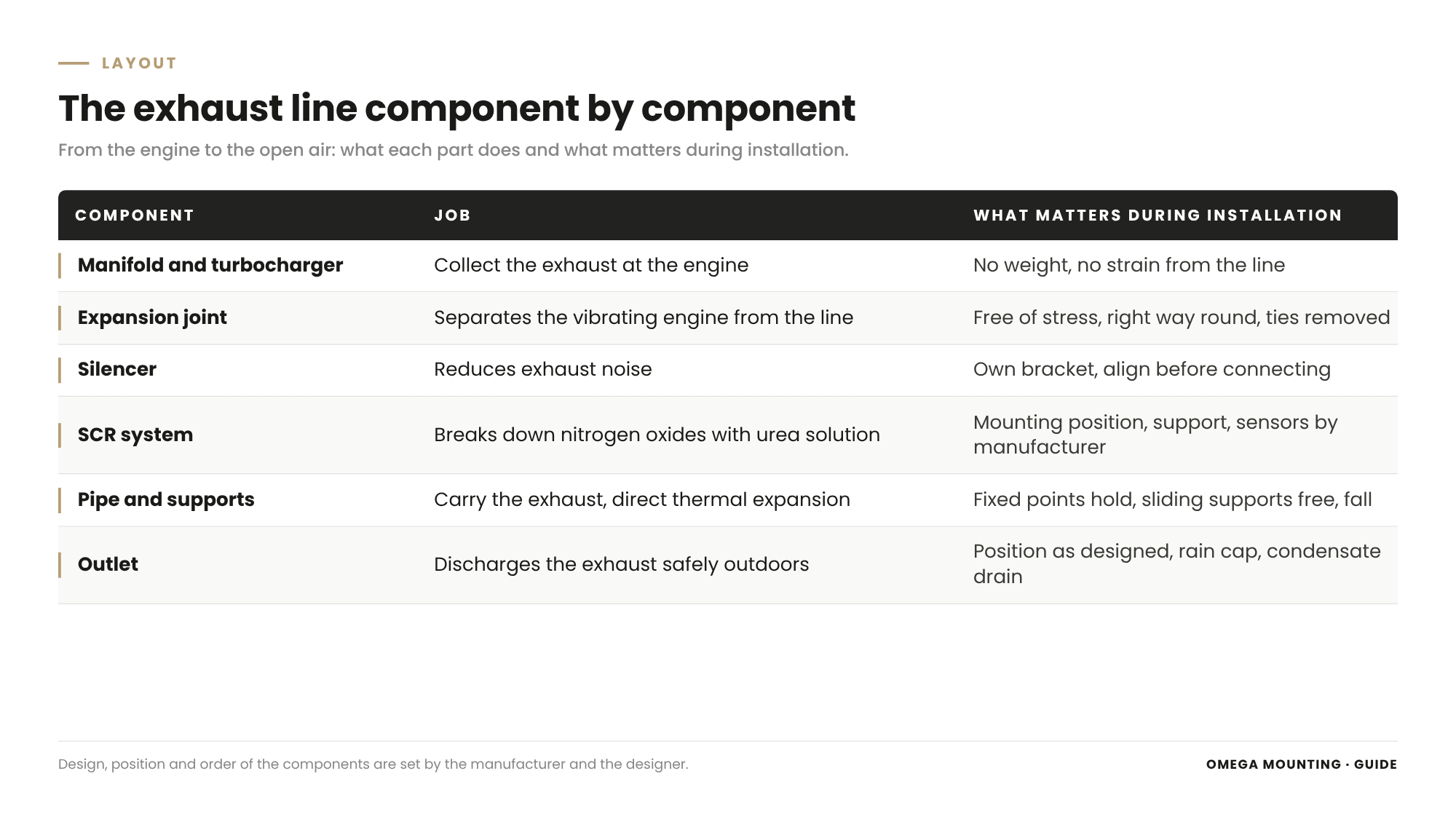
Every component of the exhaust run has its own task – and its own point where something can go wrong during installation.
Manifold and turbocharger
The manifold collects the exhaust gas from the cylinders and leads it to the turbocharger. It is part of the engine and comes from the manufacturer. The actual line begins at the turbocharger outlet. This point is sensitive: it must take neither weight nor stress from the line.
Expansion joint
The expansion joint, often a stainless steel bellows, separates the vibrating engine from the fixed line. It therefore sits directly behind the engine. Further expansion joints absorb thermal expansion between two fixed points on long runs.
Silencer
The exhaust silencer reduces exhaust noise. Silencers are heavy and need their own support. What the various silencers on a generator do is explained in the article silencer on a standby generator.
SCR-System
Many newer plants have an SCR system that breaks down the nitrogen oxides in the exhaust gas using urea solution. It sits in the exhaust path and needs space, dosing, lines and sensors. How this works is described in the article The SCR catalyst on a standby generator.
Pipes, bends and supports
Steel or stainless steel pipes run between the components. They are flanged or welded, led around obstacles with bends and held at fixed points, sliding supports and spring hangers.
Outlet
At the end is the outlet: usually a riser above the roof with a rain cap or rain flap. Its position and height come from the design and often from the permit.
Planning: back pressure, outlet and clearances come from the manufacturer and designer
An exhaust line is not invented on site. The values that decide how it works are in the manufacturer's and designer's documents.
Exhaust back pressure
Every engine tolerates only a certain exhaust back pressure. The manufacturer states the permissible value. The designer sizes cross-section, length, bends, silencer and SCR system so that the line stays below it. Anyone who adds an extra bend on site or chooses a smaller cross-section changes this calculation. Such changes therefore always go back to the designer.
Outlet and height
Where and how high the exhaust gas leaves depends on the building, the surroundings and the conditions of the permit. This is set by the designer. For the installation, what counts is that the outlet is built as designed.
Clearances
Exhaust gas must not get into supply air openings, the radiator intake or windows. Hot lines need clearance from combustible components, cable trays and other lines. The clearances come from the manufacturer's specification and the fire protection design.
Loads
Silencers, SCR systems and risers put considerable loads on floors, walls, brackets and the roof. Whether the structure can take them is checked by the structural engineer. How loads and openings are planned for bringing equipment in is described in the guide Planning a move-in operation: floor loads, openings and crane standing areas.
Design check on site
Before installation we compare the routing plan with the room: do heights and routes fit? Are beams, ventilation ducts or cable trays in the way? Where can a fixed point really be anchored? Anything that does not fit is clarified with the designer before the first pipe is hung.
The sequence: installing an exhaust line in six steps
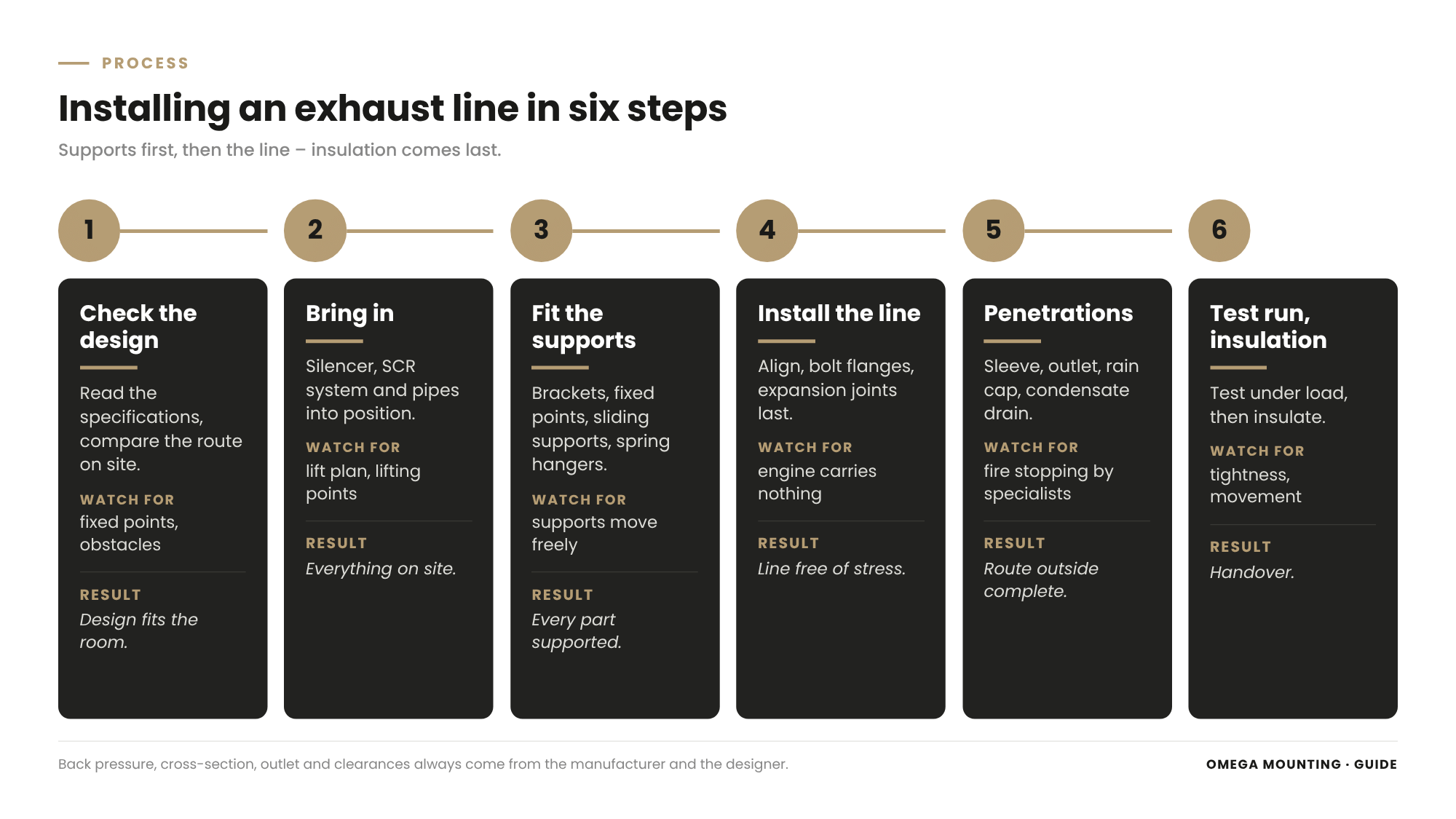
A clean installation follows a fixed sequence. Anyone who sticks to it does not have to touch anything twice.
Check the design
Read the manufacturer's and designer's documents, compare the route on site, clarify the support plan and the position of the fixed points. Open questions go to the designer before installation.
Move-in
Bring the silencer, SCR system and pipes into place along the planned route. The lifting plan defines who lifts what and with what.
Set the supports
Install brackets, fixed points, sliding supports and spring hangers before the line arrives. That way every component has its support from the start.
Install the line
Set the silencer, hang the pipes, align them, flange or weld them. The expansion joints go in last, into a line that has been aligned free of stress.
Penetrations and outlet
Complete wall and roof penetrations, riser, rain protection and condensate drain. Fire-rated penetrations are sealed by the specialist contractor.
Test run and insulation
Accompany the test run under load, check tightness and movements. Only then is the line insulated and the contact protection fitted.
Bringing in and setting heavy silencers
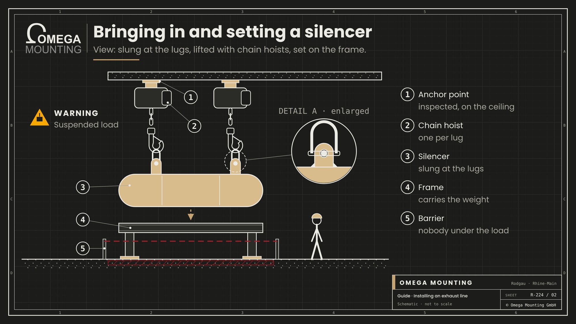
An exhaust silencer is a large, heavy component. It is brought in like a machine – with a plan, lifting equipment and clear responsibility.
Weight and lifting points
Weight, centre of gravity and lifting points are in the manufacturer's documents. Slinging is only done at the lugs or eyes provided, never on nozzles or flanges. Who is responsible for the lift is described in the guide Appointed person for lifting operations.
The route into the generator room
If the generator room is on an upper floor, the silencer comes in through a façade opening by crane, via a goods lift or on heavy-duty skates. Inside the building we work with electric equipment, chain hoists, gantries or fork lifts. How an opening for later replacement parts is planned is described in the guide Planning an installation opening.
Lifting to installation height
Many silencers sit high above the generator set or below the ceiling. Chain hoists on tested lifting points or a fork lift raise them to installation height. Nobody stands under the suspended load. The area is cordoned off.
Bracket, frame or suspension
The silencer rests on its own bracket or frame, or hangs from a suspension. This substructure carries its weight – not the line, and certainly not the engine. Its design and anchoring come from the structural engineer or manufacturer.
Align before connecting
The silencer is aligned before the pipes are connected. Flanges must be in line and parallel. Anything that is wrong here cannot be rescued later with an expansion joint.
Supports: fixed points, sliding supports and thermal expansion
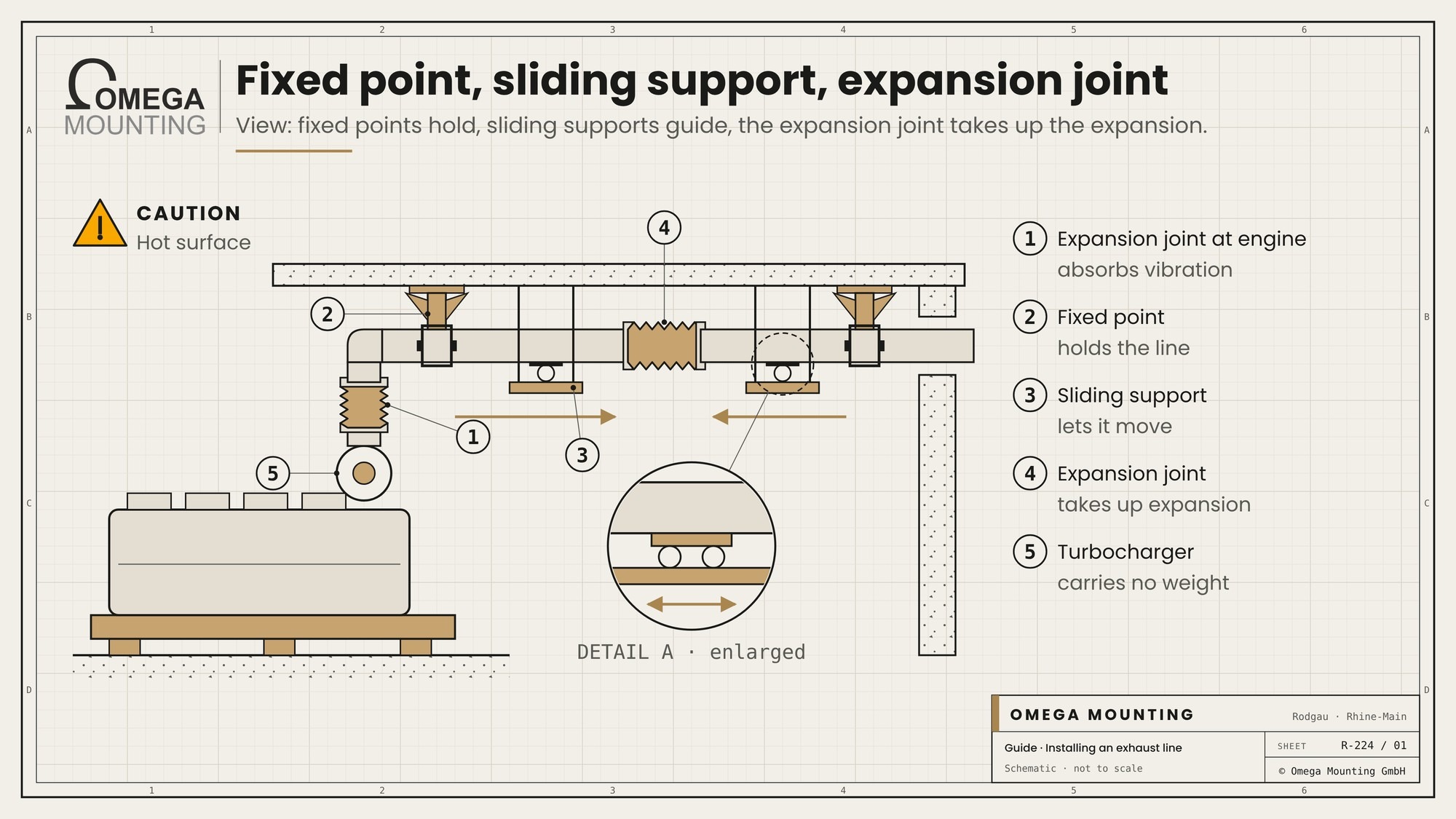
The supports are the backbone of the exhaust line. They decide whether the line works quietly in operation or whether it pushes, tears and rattles.
Understanding thermal expansion
An exhaust line gets very hot in operation and noticeably grows in length. When it cools down, it contracts again. This movement cannot be prevented. It has to be directed in a direction where it does no harm.
Fixed point
A fixed point holds the line at one fixed position. From there it expands in both directions. Fixed points sit on load-bearing components and are anchored as the support plan specifies. One fixed point too many on an exhaust line is just as bad as one too few: the line can then no longer expand.
Guides and sliding supports
Between the fixed points, guides lead the line. Sliding or roller supports let it move lengthways and keep it on track sideways. They must remain free to move. A sliding support blocked by a weld or a tightened clamp becomes an unplanned fixed point.
Spring hanger
Spring hangers carry the weight of vertical or suspended sections while allowing movement. They are set as specified. Their installation lock is only removed when the line is hanging completely.
The engine carries nothing
The turbocharger and manifold must not take any weight from the line. The first fixed point or support therefore sits close behind the expansion joint at the engine. Anyone who temporarily hangs the line on the turbocharger risks cracks in the housing.
Supports before the line
We install the supports before the pipes arrive. Then every pipe section hangs securely straight away, and nobody has to prop up a heavy line temporarily.
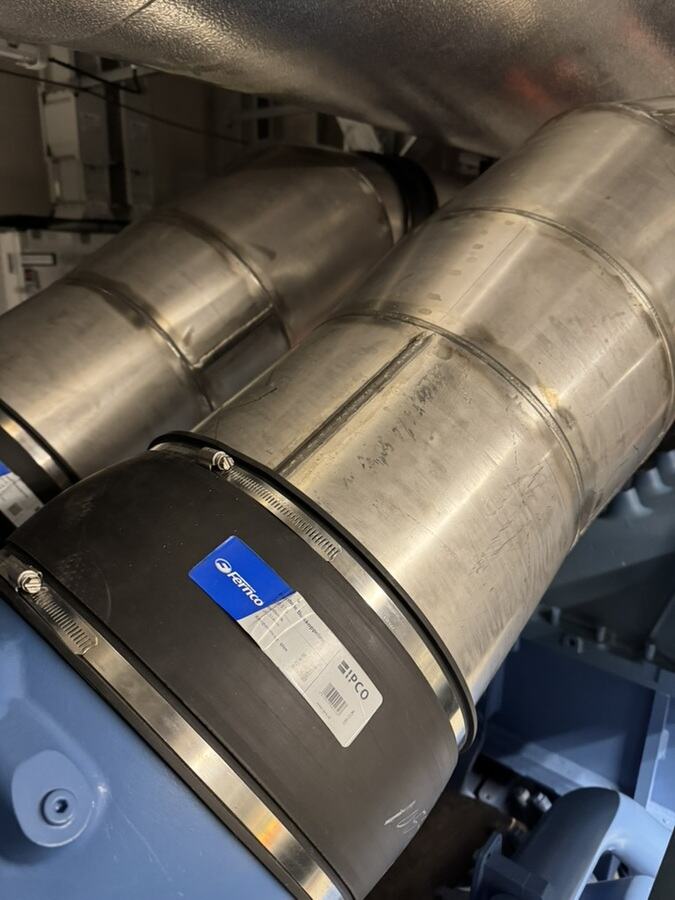
Fitting expansion joints correctly – no compensation for installation errors
The expansion joint is the component most often mistreated on site. It is made for movement in operation – not for misalignment from installation.
What the expansion joint is for
The expansion joint at the engine absorbs the vibrations and small movements of the generator set. Expansion joints in the line absorb thermal expansion between two fixed points. Both only work if the bellows sits free of stress when installed.
Not a make-up piece
If two flanges are skewed or offset, the expansion joint is not the solution. Anyone who stretches, compresses, shifts sideways or twists it to close a gap takes away its reserve for operation. The bellows fatigues and tears. The expansion joint therefore always goes last into an exhaust line that is already cleanly aligned.
Flow direction
Many expansion joints have an inner sleeve that protects the bellows from the exhaust flow. They may only be fitted in one direction. The arrow on the expansion joint points in the direction of flow – away from the engine.
Transport securing
Expansion joints are often supplied with installation tabs or locking rods that hold the bellows at installation length. They stay on during installation and come off before the first run. A forgotten transport lock turns the expansion joint into a rigid pipe.
Avoiding twist
A bellows cannot tolerate twisting around its own axis. When tightening the flange bolts, the joint is held against so that it does not turn with them.
Protection during nearby work
Welding spatter, grinding sparks and falling tools damage the thin bellows. If welding or grinding is done nearby, we cover it.
Flanges and gaskets: tight under heat and vibration
An exhaust line must be tight. Leaking flanges let hot exhaust gas into the room, soot up components and can trigger fire detectors.
Seals
Only gaskets approved for the temperature and medium are used – as specified by the manufacturer. Old gaskets are never reused.
Flange faces
The sealing faces must be clean, flat and undamaged. Rust, old gasket residue and welding spatter are removed beforehand.
Bolts and tightening
Bolts and nuts must suit the temperature. They are tightened evenly in a cross pattern, to the manufacturer's torque. How a flange connection is built correctly is explained in the article The flanged joint.
Retightening
Some manufacturers require flange bolts to be checked after the first warm run and cooling down. This is then in the test plan and is done after the test run.
Welded joints
Where pipes are welded, a hot work permit, a fire watch and protection of the surroundings are needed. How hot work in plants is organised is described in the guide repair welding on industrial plant.
Integrating the SCR system and measuring ports
On plants with exhaust after-treatment, the SCR system sits in the line. It changes the installation.
Installation position and distances
The SCR system requires a specific installation position, straight pipe sections before and after the catalyst and space for the dosing. All of this is in the manufacturer's specification.
Its own support
The SCR system also carries itself. It rests on its own brackets or a frame and, like the silencer, is connected to the line with expansion joints.
Sensors and dosing
Temperature sensors, other sensors and the urea dosing are connected by the manufacturer or an electrical contractor. Our own electricians connect on the equipment side up to the main switch. Controls, parameters and commissioning remain with the manufacturer.
Measuring ports
To measure back pressure and exhaust values, the line needs measuring ports at the planned positions. They stay accessible and are not hidden under the insulation later.
Through wall and roof: penetrations and fire protection
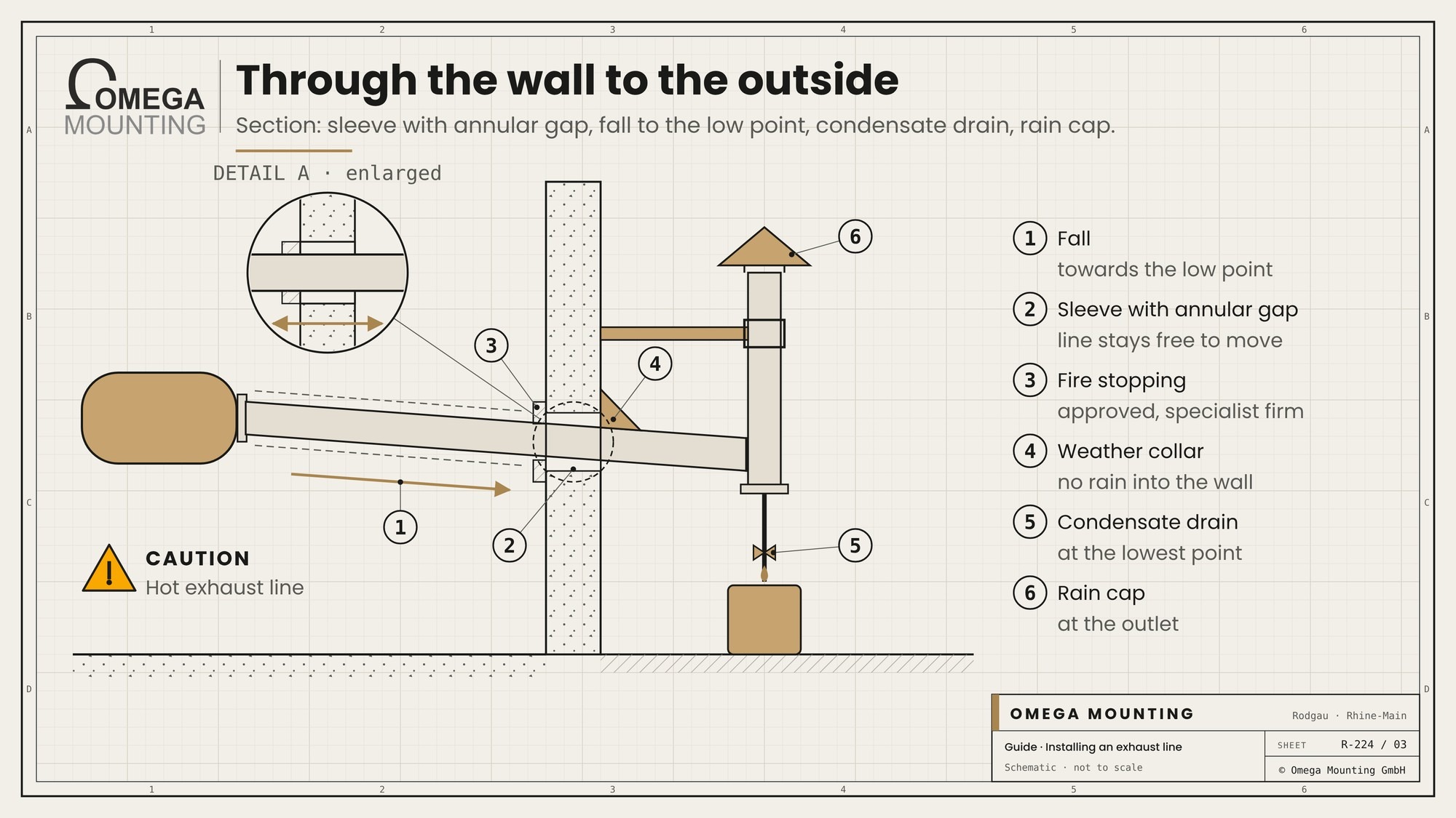
Where the exhaust line leaves the generator room, heat, movement and fire protection meet.
Sleeve and annular gap
The line does not run rigidly through the wall. It passes through a sleeve with an annular gap so that it can expand and move without rubbing against the masonry. How penetrations are drilled is described in the guide Core drilling in industry.
Fire protection
If the exhaust line passes through a fire wall or a fire-rated floor, an approved design is needed. Fire protection on the exhaust line is specified by the fire protection designer; a specialist contractor carries it out and documents it. We prepare the opening and the line so that the specialist contractor can install the fire stopping cleanly.
Weather protection
Outside, a weather collar ensures that no rain runs along the pipe into the penetration. The roof is connected by the roofer.
Riser on the roof
The riser above the roof is exposed to wind and weather. It needs its own guying or support according to the structural design and must still be able to expand.
Clearance from components
Timber, insulation, cables and plastic pipes do not belong near a hot line. The necessary clearances come from the manufacturer's specification and fire protection design and are maintained during installation.
Condensate and rain: gradient, drain and rain protection
On a cold start, water condenses in the cold line. Added to this is rain that can enter via the outlet. Neither may run back to the engine.
Fall
Horizontal runs are given a fall away from the engine – as specified by the designer. That way water does not run to the turbocharger.
Condensate drain
At the lowest point of the line there is a condensate drain. Condensate from the exhaust line is not clean and is collected and disposed of as specified by the operator.
Rain cap or rain flap
At the outlet, a rain cap or rain flap keeps water out. Flaps must stay free-moving so that they open on start-up and close again afterwards.
Avoiding low points
Every unplanned low point in the line becomes a water trap. That is why the height of every section is checked during installation – especially after bends and at penetrations.
Insulation and contact protection: test first, then wrap
Insulation keeps heat away from the room, protects people from hot surfaces and components from excessive temperatures.
Only after the test run
Insulation is only fitted once the line has been tested under load. Otherwise a leaking flange under finished insulation stays undetected until the insulation soots up or burns.
What stays free
Expansion joints, measuring ports, the condensate drain and flanges that need to be inspected stay accessible. They often get removable insulation cushions that can be released without tools.
Who insulates
The insulation of the exhaust line is often carried out by an industrial insulation contractor. We agree the sequence, access and dates with them so that they get a finished, tested line.
Contact protection
Where people pass by or work, additional contact protection is needed: guards, sheet metal or clearance. This applies especially to maintenance routes, stairs and platforms.
Weather protection outside
Outside, sheet metal cladding protects the insulation from rain. Wet insulation does not insulate and lets the line rust.
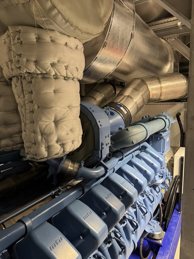
Test run with load bank and acceptance
Whether an exhaust line has been installed well only shows when the generator set runs under load. Idling is not enough for this.
Load bank
For the test run under load, a load bank is usually connected. How its location, delivery, cable route and exhaust air are prepared is described in the guide Preparing a load bank test.
What we watch during the test run
We accompany the test run: are all flanges tight? Do expansion joints and sliding supports move as planned? Does the line press against a wall or a support anywhere? Is anything rattling? Are neighbouring components getting too warm?
Measurements
Back pressure and exhaust values are measured by the manufacturer or a commissioned measuring body at the measuring ports provided. The assessment lies with them.
After cooling down
After the test run, flanges, supports and expansion joints are checked once more. Only then do insulation and contact protection follow.
Documentation
The support plan, test points, photos and open items go into the handover. How an installation in a data center is documented and accepted is described in the guide Commissioning a data center installation.
The exhaust line on a standby generator in a data center
In a data center, special rules apply to the exhaust run because the emergency power supply must not be put at risk under any circumstances.
Redundancy and time windows
When work is carried out on the exhaust line of an existing generator set, that set is not available. The work is therefore scheduled in agreed time windows in which the other generator sets secure the supply.
Permits and fire detectors
Every work step is registered with the operator. Welding and grinding need a hot work permit. Fire detectors in the area are monitored or covered by arrangement – this is controlled by the operator.
Cramped generator rooms
Generator rooms are often tightly packed: radiator, silencer, tanks, switch cabinets. Every support must leave maintenance and replacement routes free. How to think about later maintenance during installation is described in the guide Maintenance-friendly installation.
Data center exhaust run in the city
Many data centers in Frankfurt and Offenbach are in the city, with offices and flats nearby. There, noise attenuation and an outlet that discharges the exhaust gas safely count twice over. What belongs to a standby power plant is explained in the article The standby power system.
Safety rules when installing the exhaust line
- No installation without a risk assessment, briefing and lifting plan.
- Nobody works alone; every team includes a trained first aider.
- Nobody stands under suspended loads; the lifting area is cordoned off.
- Welding and grinding only with a hot work permit and fire watch.
- Work on an existing line only when the generator set is secured against starting.
- After a run the line is hot – let it cool down first, then touch it.
- Work at height only from a mobile elevating work platform or scaffold with fall protection.
Typical mistakes on the exhaust line of a standby generator
Line hanging on the turbocharger: The housing cracks, the engine is damaged.
Expansion joint used as a make-up piece: The bellows is pre-stressed and tears after a few runs.
Transport lock forgotten: The expansion joint does not work, the line pushes.
Sliding support blocked: The line cannot expand and pushes supports or walls.
Expansion joint the wrong way round: The inner sleeve faces against the flow, the bellows suffers.
No fall, no condensate drain: Water runs back to the engine.
Insulated too early: Undichte Flansche bleiben unsichtbar.
Bend added afterwards: The back pressure rises without the designer knowing.
The mistake behind the mistakes
Most mistakes happen because the exhaust line is seen as a pipe that somehow has to get outside. But it is a system of hot, heavy and moving parts. Anyone who plans and installs it that way gets no surprises in the test run.
Who does what on the exhaust line of a standby generator?
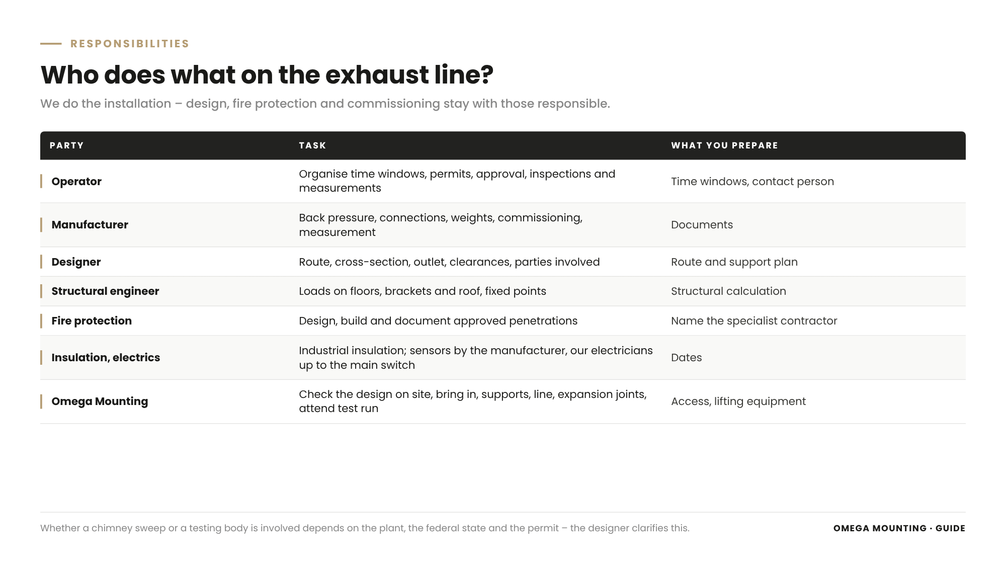
Operator
They set time windows, access and permits, organise approvals, inspections and measurements and coordinate the companies on their site.
Generator set manufacturer
They specify permissible back pressure, connections, weights and installation requirements, often supply the silencer and SCR system, commission the plant and take measurements.
Designer
They plan the route, cross-section, outlet and clearances, calculate the back pressure and coordinate the permit. Whether a chimney sweep or a measuring body has to be involved depends on the plant, the federal state and the permit – the designer clarifies this in advance.
Structural engineer
They check loads on floors, brackets and the roof and define fixed points and anchorages where large forces occur.
Fire protection designer and specialist contractor
They plan and build approved penetrations through fire walls and floors and document them.
Insulation and electrics
An industrial insulation contractor insulates. Sensors and controls are connected by the manufacturer or an electrical contractor, and by our electricians on the equipment side up to the main switch.
Omega Mounting
We check the design on site, bring in silencers, SCR systems and pipes, set supports, install and align the line, fit expansion joints, flange or weld, prepare penetrations, accompany the test run and coordinate the interfaces.
Installing an exhaust line: what it means for your planning
Are all specifications available?
Make sure that the manufacturer's specifications, routing plan, support plan and structural calculations are available before installation starts.
Is the delivery route clear?
Check how the silencer and SCR system will get into place – opening, lift, floor load, lifting equipment.
Who is responsible for fire protection?
Name the specialist contractor for the penetrations and agree the sequence with the installation.
When is it tested and insulated?
Schedule the test run, measurements and insulation as fixed steps with dates.
What belongs in the order for the exhaust line
Service
Design check on site, bringing in, supports, installation of the line with silencer, SCR system and expansion joints, preparation of penetrations, accompanying the test run.
The frame
Time windows, access, lifting equipment, hot work permits, interfaces with the manufacturer, fire protection, insulation and electrics.
Record
Support plan with fixed points, test points, photos, test run record and list of open items.
Legal framework
The exhaust system of a standby power plant is subject to, among other things, emission control law for exhaust gas and noise, the building regulations of the respective federal state with their fire protection requirements, the Ordinance on Industrial Safety and Health for lifting work and work equipment, and the Occupational Safety and Health Act with its duty to carry out a risk assessment. In addition, there are the standards for generating sets, the manufacturer's specifications and the conditions of the permit. This guide is not legal advice – which duties apply in your case should be clarified with your designer, your permitting authority and your occupational safety specialist.
Installing an exhaust line in the Rhine-Main area: how we work
From Rodgau we reach Frankfurt, Offenbach, Hanau, Darmstadt and the region's data center sites quickly – and we work nationwide with our own teams. Anyone in Rhine-Main who wants an exhaust line for emergency power installed gets bringing in, supports, installation and coordination from a single source with us.
We have brought in standby generators, built them as indoor solutions with exhaust runs, retrofitted silencers and carried out repairs on standby power plants. How we work in data centers is shown on the page on data center installation.
For you, that means one contact for lifting, assembly and interfaces.
Project examples
Three jobs show what matters on the exhaust run – one directly, two as related jobs.
Exhaust run in the generator room
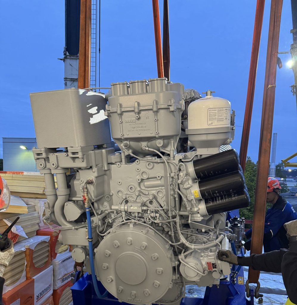
In a data center in the Frankfurt area we brought in standby generators and built them as an indoor solution from individual assemblies – with manifold and further exhaust run, silencer and SCR system. Where a moving assembly is connected to a rigid one, there is a flexible section. Our job ended when the plant was ready for commissioning. The test run under load, parameter setting and acceptance were carried out by the manufacturer. The job is described in the report Standby generator installation in data centers.
Silencers without a crane
In a data center in Offenbach we retrofitted turbo silencers – on the intake side, not in the exhaust path. But the tasks were related: the heavy silencers came up to the floors via goods lifts and were lifted with crank-operated fork lifts onto their own base frames above the generators. The welded stainless steel pipework is decoupled from the vibrating engine with rubber sleeves. Measurements were taken under full load, inside and outside. The job is described in the report Turbo silencers at a data center in Offenbach.
Barely a hand's width of space
On a standby generator in a data center in Offenbach we sealed a leak on the radiator on site. This job had nothing to do with the exhaust line. But it shows what happens when there is no space around a generator set: there was barely a hand's width between the radiator and the ventilation grille with silencer, and the hot work permit was organised in advance. The job is described in the report Radiator repair on a standby generator.
Do you have an exhaust line coming up?
Send us the routing plan, manufacturer's documents and photos of the generator room – we will tell you what the installation can look like. Get in touch now.
What this means for your role
Operators and technical managers: Schedule work on the exhaust line in time windows in which the other generator sets secure the supply.
Planners: Supply a routing and support plan with clearly defined fixed points and clarify the outlet, clearances and parties involved in advance.
Project and site managers: Put the test run and insulation into the schedule as separate steps.
Service companies: During maintenance, check whether sliding supports run freely and expansion joints sit free of stress.
Buyers: Ask whether bringing in, supports, penetrations and accompanying the test run are included in the quotation.
Occupational safety specialists: Check the lifting plan, hot work, contact protection and fire protection of the penetrations.
Exhaust run checklist: template on request
For installing an exhaust line we have put together the Exhaust Run Checklist. It covers the manufacturer's specifications, route and outlet, weights and delivery route, supports, expansion joints, flanges, penetrations, condensate, insulation and test run. Request the template via our contact form an – Stichwort „Checkliste Abgasstrecke“.
Why Omega Mounting?
From more than twenty years of practice in installation, rigging and maintenance we know: on an exhaust line, the first run under load decides how carefully it was installed. We have brought in and built generators and silencers in data centers and know the pitfalls between lift, support and expansion joint. Rigging, installation and equipment-side electrics come from a single source, and we never send just one fitter. For you this means: an exhaust run that is tight in the test run. Talk to us about your plant – we will get back to you promptly.
Conclusion
Installing an exhaust line on a standby generator means implementing the manufacturer's and designer's specifications, bringing in heavy components safely, setting fixed points and sliding supports so that the line can expand freely, and fitting expansion joints free of stress and the right way round. Added to this are tight flanges, penetrations with an annular gap and approved fire protection, a clean condensate drain and insulation that only follows the test run.
Anyone who plans and installs the exhaust run as a system gets no surprises during the run under load. If you would like an exhaust line installed on a standby generator, get in touch with us.
Planning a move-in, installation or maintenance in the Rhine-Main region?
Tell us briefly what you need – we'll come back with an honest assessment.
Free, no-obligation callback
You may also be interested in these guides

About the author
Tobias Schott
Managing director of Omega Mounting GmbH, Rodgau · more than 20 years of hands-on experience in installation and maintenance
A trained mechatronics technician, working in maintenance, servicing and industrial installation since 2004 – first alongside his father, and with Omega Mounting since 2012: from overhead conveyors in Frankfurt to the crane system in a new-build hall. He plans and leads lifting operations as an appointed person (AP) in data centers and on industrial sites in the Rhine-Main region, trains and examines operators of cranes, mobile elevating work platforms and telehandlers, and is a qualified occupational safety specialist. On jobs abroad he is known as the “German Troubleshooter” – the person you call when a site gets stuck. He learned what quality means from his father, not from a manual: Made in Germany as a standard for his own work, not a label. That is why quality comes first at Omega Mounting – ahead of speed and price. He writes these guides from that practice: what works on our sites is in them – what exists only on paper is not.
Frequently asked questions
Manifold, expansion joint, silencer, an SCR system on many newer plants, pipes with bends, supports, penetrations, condensate drain, insulation and the outlet with rain protection.
The manufacturer states the permissible exhaust back pressure of the engine. The designer sizes cross-section, length and components so that the line stays below it.
It separates the vibrating engine from the fixed line and absorbs thermal expansion between two fixed points on long runs. It does not compensate for installation errors.
A fixed point holds the line at one position. A sliding support guides it and lets it move lengthways so that it can expand when hot.
With a lifting plan, at the lifting points provided, by crane through an opening or inside the building with chain hoists or a fork lift – and set on its own bracket or frame.
Only after the test run under load, when all flanges are tight. Expansion joints, measuring ports and the condensate drain stay accessible.
The fire protection designer specifies the design; a specialist contractor installs the approved fire stopping and documents it. We prepare the opening and the line for this.
Yes. From Rodgau we are quickly on site in the region, and we work throughout Germany with our own teams.
Send us the routing plan, manufacturer's documents and photos of the generator room. We will check the documents and get back to you with a proposal. Go to the contact page.
 English
 German