
- Technology explained – technology and procedures
The flanged joint: gasket, bolts and tightening in a cross pattern
By Tobias Schott · 6-minute read · Updated November 2026
A flanged joint connects pipes, valves and pumps in a way that can be undone: two flanges compress a gasket by means of bolts – it only seals if faces, gasket and tightening all match.
Every industrial plant has hundreds of flanged joints. They sit on pumps, valves, vessels, heat exchangers and wherever a pipeline will need to be separated again later. Most leaks in pipework occur right here – and almost always for the same reason: the joint was not assembled the way it has to be.
Here we explain the flange types, the role of sealing face and gasket, the correct tightening sequence and the most common causes of leaking flanges.
What is a flanged joint?
A flanged joint is a detachable connection between two components via ring-shaped collars that are pulled together with bolts, compressing a gasket in the process. In German it is called “Flanschverbindung”.
Flanges are standardised, in Europe mainly to EN 1092-1 for steel flanges. Two values identify every flange: DN for the nominal size of the pipe and PN for the pressure rating. Only flanges with the same nominal size, pressure rating and sealing face fit together.
For operators, a leaking flange is often more than a drip. Depending on the medium, it is about water damage, product loss, environmental protection or safety. And a leak rarely occurs at a quiet moment, but during start-up, the first heat-up or after a pressure surge. That is why it pays not to treat flanged joints as a side issue of pipe installation, but as a separate work step with clear specifications: the right gasket, clean faces, specified torque, documented tightening.
Key facts
- Task: Connect pipes and components tightly and detachably.
- Parts: two flanges, a gasket, bolts or studs, nuts, washers.
- Marking: Nominal size DN and pressure rating PN.
- Types: Weld neck flange, slip-on flange, lap joint flange, blind flange.
- Gaskets: Soft material, spiral wound, kammprofile, metal.
- Critical: Pipe alignment, condition of the sealing face, tightening sequence.
- Field of use: Pipework, pumps, valves, vessels, plant construction.
Flange types
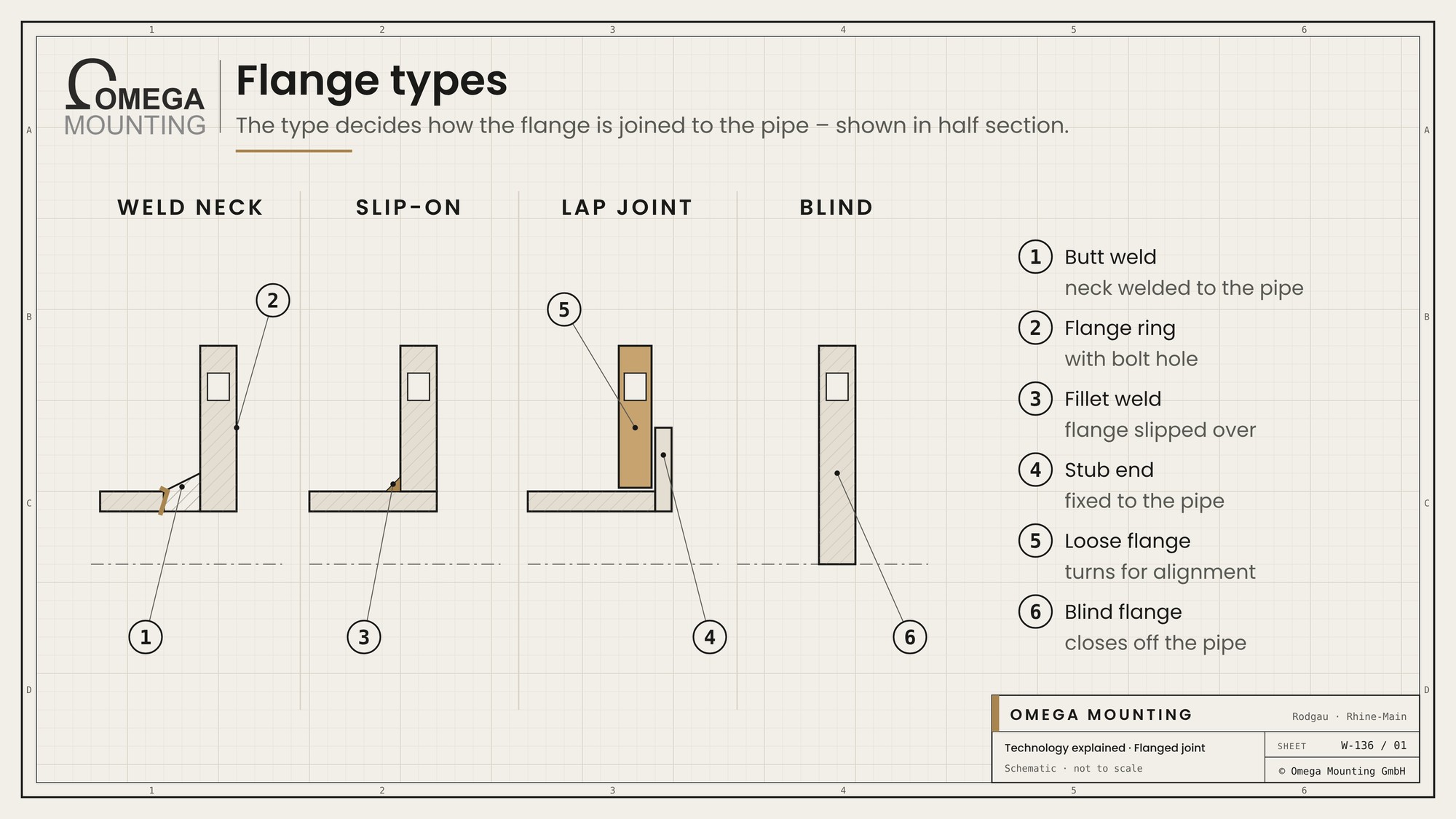
How a flange is joined to the pipe determines its type.
- Weld neck flange: has a long neck that is butt-welded to the pipe. It is robust and suitable for high pressures.
- Slip-on flange: is slipped over the pipe and welded with fillet welds. It is easier to install but less robust.
- Lap joint flange: sits loosely behind a stub end or flare on the pipe and can be rotated. This makes it easier to line up the bolt holes.
- Blind flange: closes off a pipe or nozzle completely.
Lap joint flanges are common on stainless steel and plastic pipework because the flange itself can be made of a simpler material. Only the stub end is in contact with the medium.
There are also special types such as threaded flanges for small pipes without welding, or wafer-style fittings such as butterfly valves held between two pipe flanges. Care is needed with butterfly valves: the disc must be slightly open during tightening, otherwise it jams against the pipe wall.
Sealing face and gasket
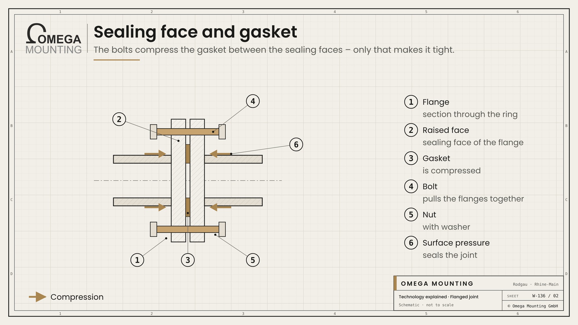
A flanged joint seals through surface pressure: the bolts press the gasket against the sealing faces so hard that the medium cannot get through.
| Gasket | Design | Typical for | Points to note |
|---|---|---|---|
| Soft gasket. | Fibre or graphite sheet. | Water, air, low pressures. | Creeps, never reuse. |
| Spiral wound gasket. | Wound metal strip with filler. | Higher pressures and temperatures. | Precise tightening needed. |
| Kammprofile gasket. | Metal ring with grooves and facing. | Changing temperatures. | Clean sealing face. |
| Metal gasket. | Solid metal ring. | Very high pressures. | High bolt forces. |
The sealing face must suit the gasket. There are flat raised faces, tongue and groove, or male and female faces. Scratches across the sealing face are dangerous because they form a channel to the outside. Grooves running round the circumference, on the other hand, are often intended because they hold the gasket better.
Tightening in a cross pattern
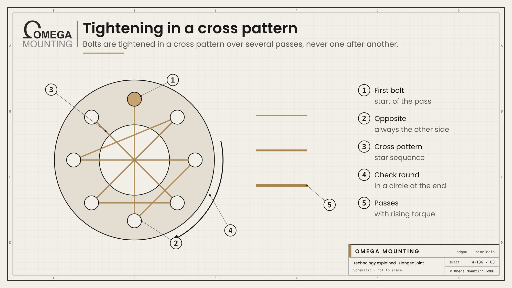
Bolts on a flange are never tightened one after another, but in a cross pattern.
- Hand-tight: All nuts are run down by hand, the gap is even all round.
- First pass: Cross pattern at part of the final torque.
- Further passes: Cross pattern with rising torque up to the final value.
- Check round: In a circle until no nut turns any more.
The reason: if you tighten one bolt after the other, the flange tilts and the gasket is crushed on one side and barely compressed on the other. The final torque depends on bolt, gasket and lubrication and comes from the gasket manufacturer's data or the plant design. In between, the gap is measured at several points. If it is uneven, the joint is corrected before the next pass begins.
Why flanges leak
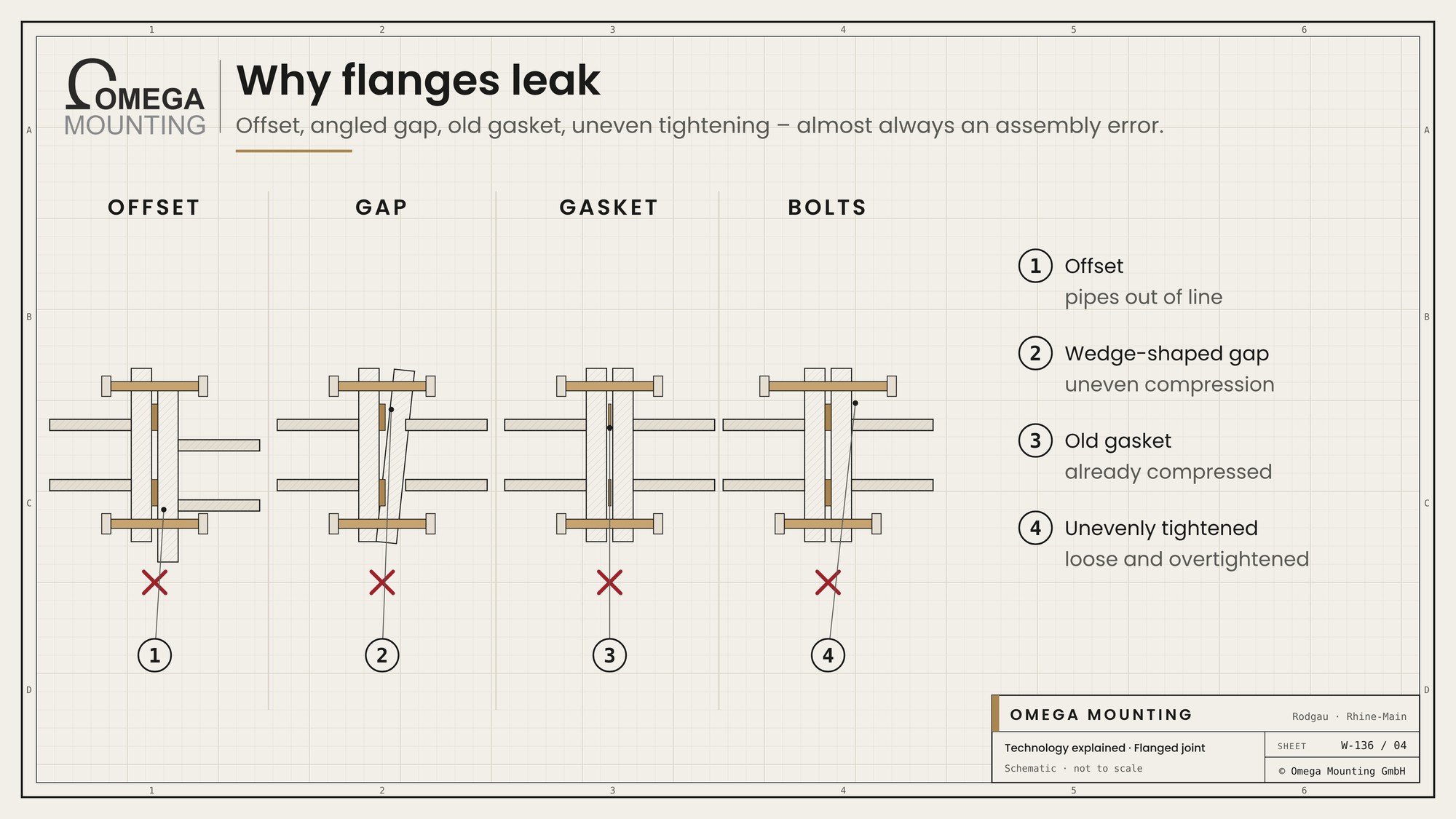
Almost every flange leak has one of these causes.
- Offset: The pipes are out of line and the flange is “pulled in” with the bolts. The pipework is under stress.
- Wedge-shaped gap: The flanges are at an angle and the gasket is compressed unevenly.
- Old gasket: A gasket that has already been compressed does not seal a second time.
- Unevenly tightened: Some bolts loose, others overtightened.
- Damaged sealing face: Scratches, corrosion or remnants of the old gasket.
- Wrong gasket: not suited to medium, pressure or temperature.
The first point is the most important. Pipework must be aligned so that the flanges sit parallel to each other without force. Anyone who compensates for offset with bolts transfers the stress into pumps and valves. The result is not only leaks but also bearing damage on pumps and sticking valves, whose cause nobody later looks for at the flange.
Pressure testing and leak checks
After installation, a pipeline is tested before the medium goes in.
- Pressure test: The line is brought to a test pressure with water or gas and held for a specified time. If the pressure drops, there is a leak somewhere.
- Visual check: With water, drips show at the flanges. With gas, leak detection spray is used to look for bubbles.
- Documentation: Test pressure, duration and result go into the record.
One rule matters: retightening is only done without pressure. Turning a leaking flange under pressure risks blowing out the gasket or snapping a bolt. First depressurise, then tighten, then test again.
On lines that get hot, retightening after the first heat-up may be specified because the gasket settles. Whether this is necessary is stated in the gasket manufacturer's data. Lines carrying hazardous media are subject to stricter tests, specified by the operator and its inspectors.
What we pay attention to
With flanged joints we work carefully, because rework under pressure is costly and dangerous.
- We align pipework so that the flanges sit stress-free in front of each other.
- We clean and inspect sealing faces before a gasket is fitted.
- We use only new gaskets of the specified type.
- We tighten in a cross pattern over several passes, with calibrated tools.
- We document tightened joints for the pressure test and acceptance.
Where we use it
With the Installation of a hydropower plant in an existing building we brought in the hopper with chain hoists while pumps kept the excavation dry. The brackets were welded and set in concrete the next day. In work like this, alignment and clean connections decide whether the installation later runs tight and stress-free. More on this on our page on Industrial installation.
More technology explained
Do you have questions about how this works on your site?
Do you have questions about how pipework and flanges are installed on your site? We align, connect and document. Request a callback.
Free, no-obligation callback
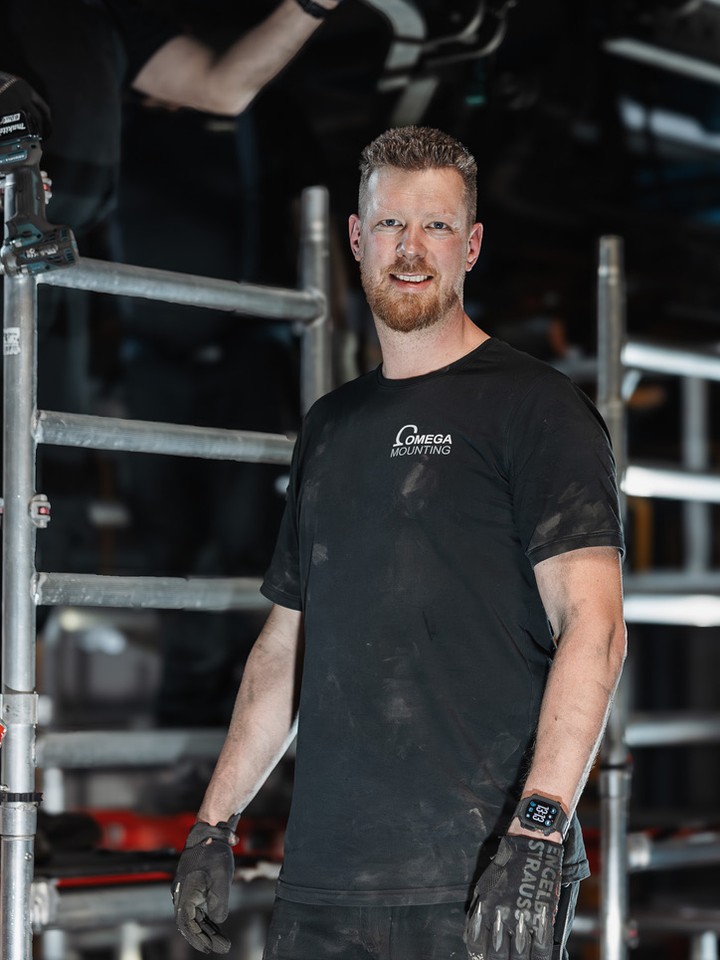
About the author
Tobias Schott
Managing director of Omega Mounting GmbH, Rodgau · more than 20 years of hands-on experience in installation and maintenance
A trained mechatronics technician, working in maintenance, servicing and industrial installation since 2004 – first alongside his father, and with Omega Mounting since 2012: from overhead conveyors in Frankfurt to the crane system in a new-build hall. He plans and leads lifting operations as an appointed person (AP) in data centers and on industrial sites in the Rhine-Main region, trains and examines operators of cranes, mobile elevating work platforms and telehandlers, and is a qualified occupational safety specialist. On jobs abroad he is known as the “German Troubleshooter” – the person you call when a site gets stuck. He learned what quality means from his father, not from a manual: Made in Germany as a standard for his own work, not a label. That is why quality comes first at Omega Mounting – ahead of speed and price. The Technology explained articles cover the equipment and techniques his team uses every day: what counts on site is in them – what only appears in the brochure is not.
 English
 German