
- Technology explained – technology and procedures
Shaft coupling: rigid, flexible, jaw – and why alignment matters
By Tobias Schott · 5-minute read · Updated November 2026
A shaft coupling connects two shafts and transmits the torque from the motor to the machine – some compensate small alignment errors, but none makes up for poor alignment.
You encounter shaft couplings between motor and pump, motor and fan, motor and gearbox, motor and generator. They usually sit under a guard and only attract attention when a spider crumbles or a bearing fails again and again. The catalogue contains names such as jaw coupling, pin coupling or disc coupling.
This article explains which types of coupling exist, what misalignment they compensate and why alignment is still decisive. How to maintain drives as a whole is described in the guide Maintaining drives, gearboxes and pumps.
What is a shaft coupling?
A shaft coupling is a machine element that connects two shaft ends in a rotationally fixed manner and transmits the torque from the input to the output shaft. It usually consists of two hubs, which are pushed onto the shafts and secured with a feather key or clamping, and a connecting element in between.
Depending on the design, this element is rigid, made of flexible plastic or of flexible metal parts. This determines whether the coupling dampens shocks and permits small alignment errors. In German it is called „Wellenkupplung“, the jaw coupling „Klauenkupplung“.
Key facts
- Purpose: Transmit torque, connect shafts, depending on the design dampen shocks and compensate small misalignment.
- Groups: Rigid, torsionally flexible, torsionally rigid compensating, plus switchable and overload couplings.
- Typical designs: Sleeve and flange coupling, jaw coupling with spider, pin and tyre coupling, gear, disc and bellows coupling.
- Characteristics: Nominal torque, maximum speed, bore diameter, permissible misalignment according to the manufacturer.
- Wear parts: Spider, elastomer element, pin buffers, disc packs.
- Typical applications: Pumps, fans, compressors, gearboxes, generators.
- Common misconception: A flexible coupling compensates any alignment error – it only tolerates it and passes the forces on to the bearings.
Rigid, flexible, torsionally rigid: the types of coupling
Couplings differ in whether they give way – in the direction of rotation, across the shaft or not at all.
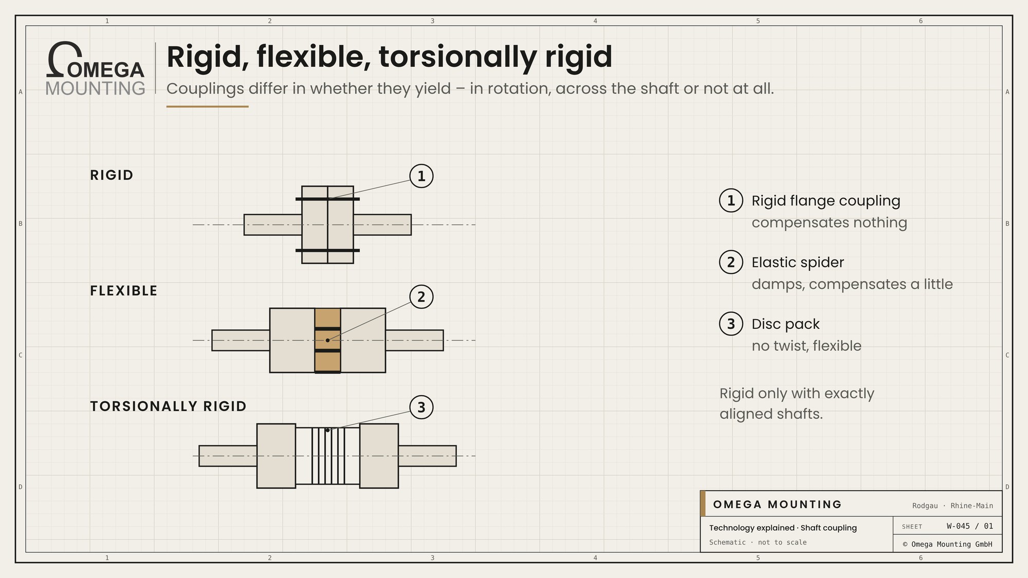
Rigid couplings. Sleeve and flange couplings connect the shafts as if they were a single shaft. They transmit large torques but compensate nothing. The shafts must be exactly aligned, otherwise they and their bearings are constantly bent.
Torsionally flexible couplings. Between the hubs sits an element made of plastic or rubber: the spider in the jaw coupling, rubber buffers in the pin coupling, a rubber tyre in the tyre coupling. They dampen torsional shocks and vibrations, protect motor and machine and permit small misalignment. The elastomer is a wear part.
Torsionally rigid, compensating couplings. Gear couplings, disc and bellows couplings transmit the torque without twisting but compensate misalignment via movable teeth or flexible metal parts. They are needed where speed or position must be transmitted precisely.
There are also overload and slip couplings that disconnect in the event of a blockage, and switchable couplings that engage and disengage drives.
Radial, axial, angular: the three types of misalignment
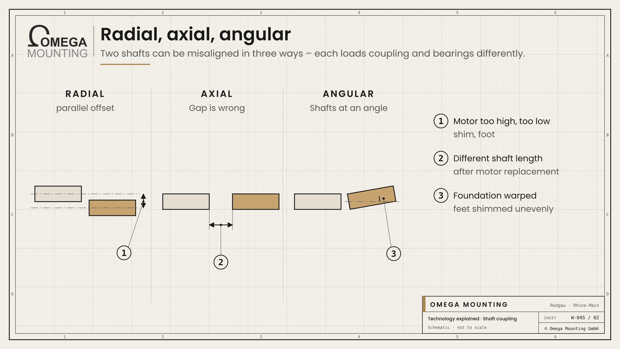
Two shafts can fail to match each other in three ways – and each loads coupling and bearings differently.
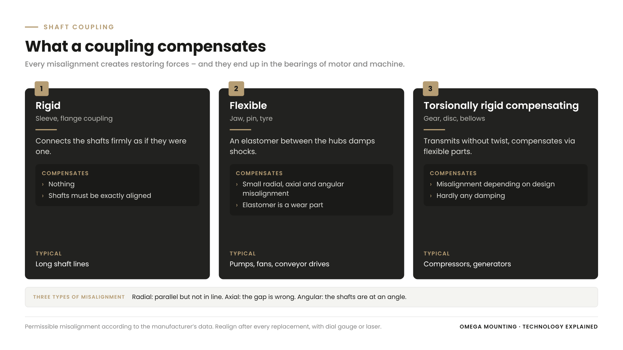
| Coupling group | Examples | Compensates | Dampens | Typical use |
|---|---|---|---|---|
| Rigid. | Sleeve, flange coupling. | Nothing. | No | Long shaft lines, exactly aligned bearings. |
| Torsionally flexible. | Jaw, pin, tyre coupling. | Small radial, axial and angular misalignment. | Yes | Pumps, fans, conveyor drives. |
| Torsionally rigid compensating. | Gear, disc, bellows coupling. | Misalignment depending on design. | No or hardly. | Compressors, generators, positioning drives. |
- Radial misalignment: The shafts are parallel but not in line, for example because a motor sits too high or too low.
- Axial misalignment: The distance between the shaft ends is wrong, for example after replacing a motor with a different shaft length.
- Angular misalignment: The shafts are at an angle to each other, for example due to a warped foundation or unevenly shimmed feet.
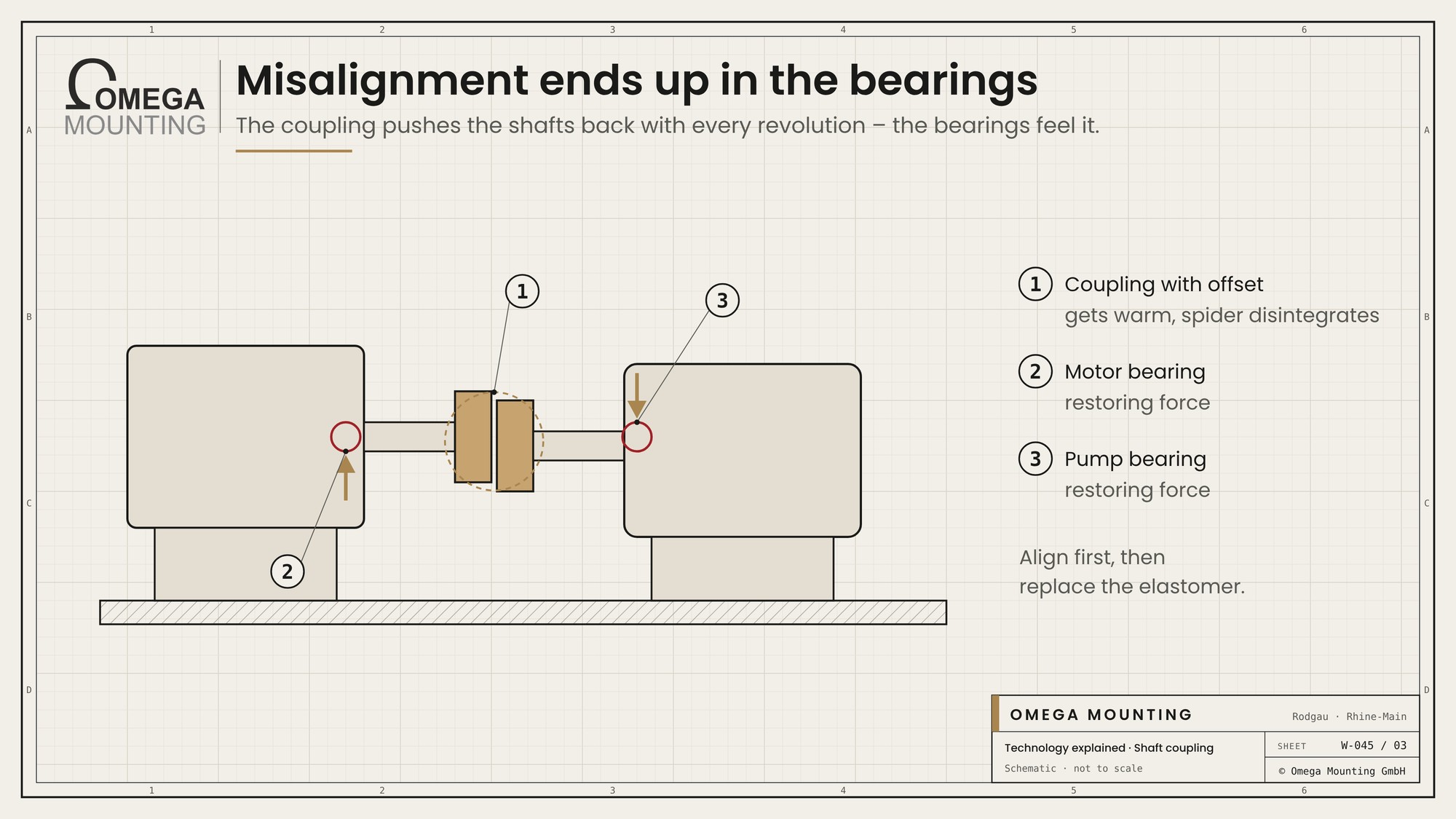
Every misalignment creates restoring forces. The coupling pushes the shafts back with every revolution, and these forces end up in the bearings of motor and machine. The consequences are heat at the coupling and bearings, vibration at once and twice the rotational frequency and premature bearing failure.
How to recognise a worn coupling
A coupling usually announces its wear before it breaks – through debris, play, heat and noise.
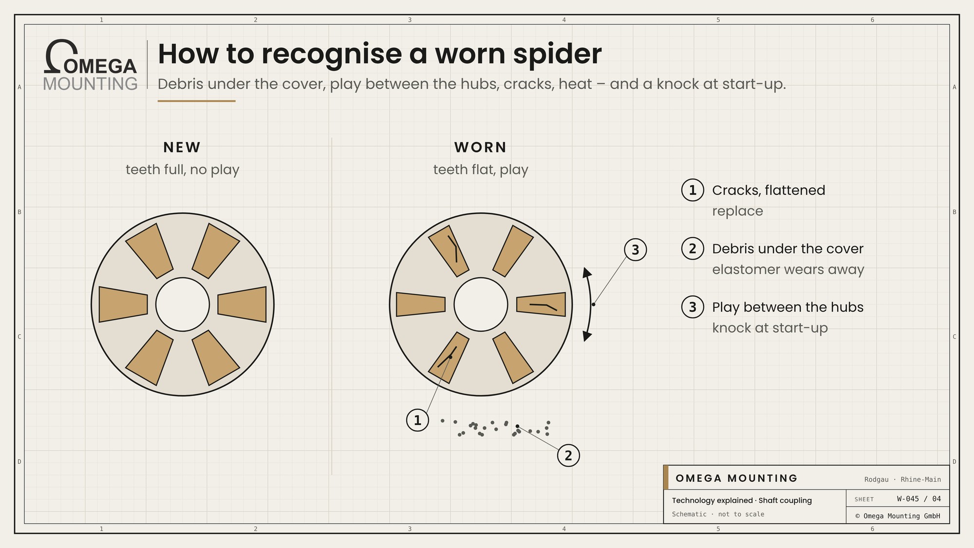
- Debris: Fine rubber or plastic dust under the guard means the spider or the buffers are wearing away.
- Play: If one hub can be turned against the other at standstill, the elastomer is worn.
- Cracks and deformation: Hardened, cracked or flattened elements must be replaced, even if the coupling is still running.
- Heat: A warm coupling points to misalignment or overload; in the thermal image it is often the clearest signal.
- Noise at start-up: A knock when switching on indicates large play or loose hubs.
A disintegrated spider is rarely the cause but the symptom. Anyone who only replaces the elastomer and does not realign will soon replace it again.
Fitting a coupling
The best coupling does not last long if it is fitted wrongly. These steps are part of it:
- Fit the hubs: Hubs are slid on or fitted warm, not knocked on. Blows damage the bearings of the motor and machine.
- Keep the axial gap: The gap between the hubs is stated in the instructions. Set too tight, the coupling presses on the bearings.
- Aligning: Radial and angular misalignment are measured and corrected with a laser or dial gauge.
- Secure the screws: Set screws and clamping screws are tightened to the specified torque and secured.
- Fit the guard: The coupling guard goes back on before the test run.
After a few operating hours a second look pays off: are the screws still tight, is the elastic spider undamaged, is the alignment still right when warm? Especially with machines that heat up a lot in operation, the position can shift.
What we pay attention to
We replace couplings according to type and size – and always realign afterwards.
- We take over design, size, bore and elastomer hardness from the old part and replace wear parts such as spiders in good time.
- We fit hubs with the appropriate tool, heated if necessary, and never with hammer blows on the shaft.
- We keep the gap dimension between the hubs according to the manufacturer’s specification.
- We align motor and machine after every replacement with a dial gauge or laser and correct with suitable shims.
- We check the feet for even contact before aligning so that the motor does not distort when tightened.
- We refit the guard before the drive starts up.
Where we use it
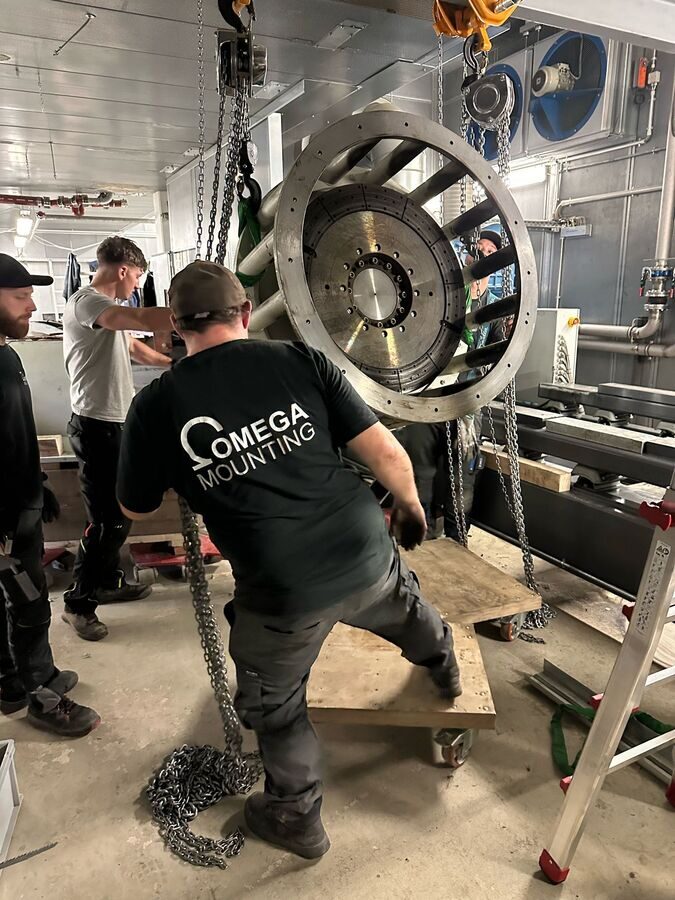
We release and connect couplings with every motor, pump and set replacement. During the generator maintenance on a standby power system the overhauled components came back the same way after the overhaul: lift in, bring in, assemble, align. In the plant room our mechanics reassembled the set, positioned the generator and connected it to the engine. Such work is part of our Maintenance and servicing.
More technology explained
Technology explained
how shafts are precisely aligned with each other.
Technology explained
how an alignment error shows up in the spectrum.
Guide
the guide when the fault lies in the foundation.
Do you have questions about how this works on your site?
Do you have questions about how this works on your site – for example, why a coupling spider on your pump keeps disintegrating? We replace, align and look for the cause. Request a callback – we will get back to you.
Free, no-obligation callback
About the author
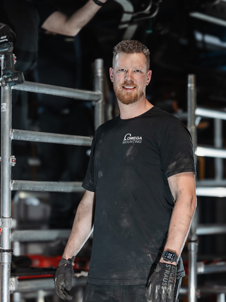
Tobias Schott
Managing director of Omega Mounting GmbH, Rodgau · more than 20 years of hands-on experience in installation and maintenance
A trained mechatronics technician, working in maintenance, servicing and industrial installation since 2004 – first alongside his father, and with Omega Mounting since 2012: from overhead conveyors in Frankfurt to the crane system in a new-build hall. He plans and leads lifting operations as an appointed person (AP) in data centers and on industrial sites in the Rhine-Main region, trains and examines operators of cranes, mobile elevating work platforms and telehandlers, and is a qualified occupational safety specialist. On jobs abroad he is known as the “German Troubleshooter” – the person you call when a site gets stuck. He learned what quality means from his father, not from a manual: Made in Germany as a standard for his own work, not a label. That is why quality comes first at Omega Mounting – ahead of speed and price. The Technology explained articles cover the equipment and techniques his team uses every day: what counts on site is in them – what only appears in the brochure is not.
 English
 German