
- Technology explained – technology and procedures
Laser alignment: machines, crane runways and racks to the millimetre
By Tobias Schott · 7-minute read · Updated October 2026
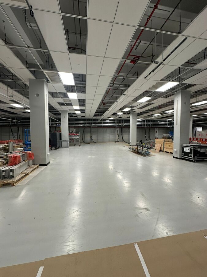
Laser alignment uses a laser beam to set a common reference plane in the room, so that machines, crane runways and rows of cabinets stand exactly where the drawing puts them – before anything is drilled, grouted or connected.
In an installation plan, laser alignment often appears as an inconspicuous line: “set out positions”, “survey runway”, “align plant”. Behind it is a work step on which a lot depends. A crane runway out of gauge wears out the wheels. A pump that stands askew ruins coupling and bearings. A row of cabinets out of line no longer fits under its cable tray.
Here we explain how laser alignment works, which measuring instruments exist, what makes laser shaft alignment special and how a measurement runs. How a crane runway is surveyed in detail or a machine anchored is covered in our guides.
What is laser alignment?
Laser alignment means measuring height, position and direction with a laser beam as the reference, against which every measuring point is read and compared with its target value. In installation work it is not used for land surveying but for alignment: it shows how far a component deviates from its target position. Recording coordinates is also called laser surveying; in German the whole field is Laservermessung.
The basic idea is old. A string line, spirit level and water level do the same. The laser simply reaches further, can be read at many points from one position and does not sag.
Key facts
- Principle: A laser sets up a reference plane or reference line; the distance of each measuring point from it is measured
- Measured values: Height (levelling), line (alignment), right angle (diagonals), distance between two rails (gauge), and for shafts offset and angle
- Instruments: Rotating laser, line laser, total station, laser alignment system for shafts and couplings
- Field of use: Machine installation, crane runways and gantries, cabinet rows in data centers, structural steelwork, pumps and drives
- Requirements: Fixed instrument position free of vibration, clear line of sight, an agreed reference point, checked and calibrated measuring equipment
- Tolerance: Set by the manufacturer or the relevant standard – never by the instrument and never by the fitter
- Result: A measurement record with target, actual and deviation for each point, before and after correction
How does laser alignment work?
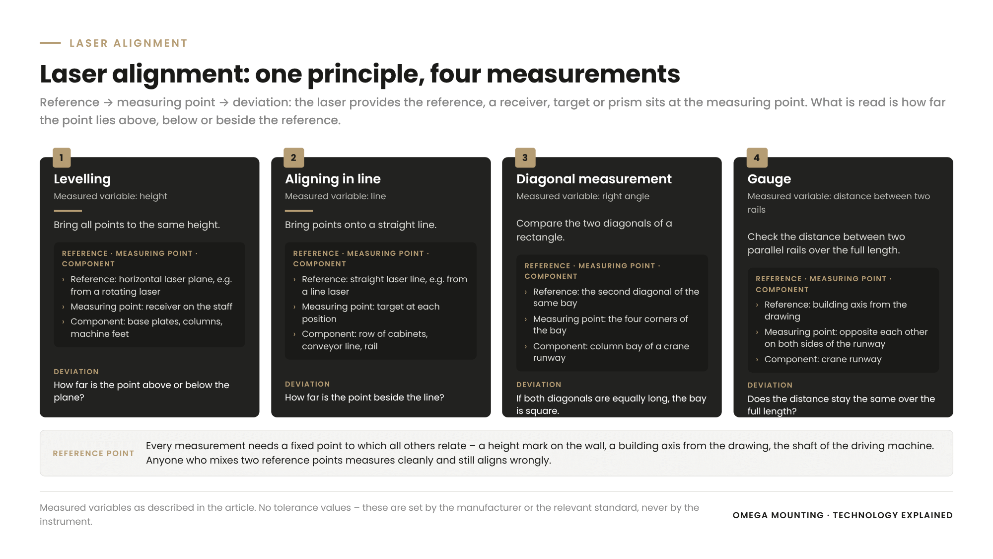
Laser alignment works through three things: a reference, a measuring point and the deviation between them. The laser provides the reference – a horizontal plane, a vertical plane or a straight line. At the measuring point sits a receiver, a target or a prism. What is read is how far the point lies above, below or beside the reference.
This gives four measured values that come up again and again in installation work:
- Levelling: Bring all points to the same height – base plates, columns, machine feet.
- Alignment: Bring points onto a straight line – a row of cabinets, a conveyor line, a rail.
- Diagonals: Compare the two diagonals of a rectangle. If they are the same length, the bay is square.
- Gauge: Check the distance between two parallel rails along their whole length, for example on a crane runway.
The reference point is what matters. Every measurement needs a fixed point to which all others relate: a datum mark on the wall, a gridline from the drawing, the shaft of the driving machine. If you mix two reference points, you measure accurately – and still align wrongly.
Which instruments are there – and what does each one measure?
Four laser instruments are common in installation work; they differ in whether they provide a plane, a line, a coordinate or the position of two shafts.
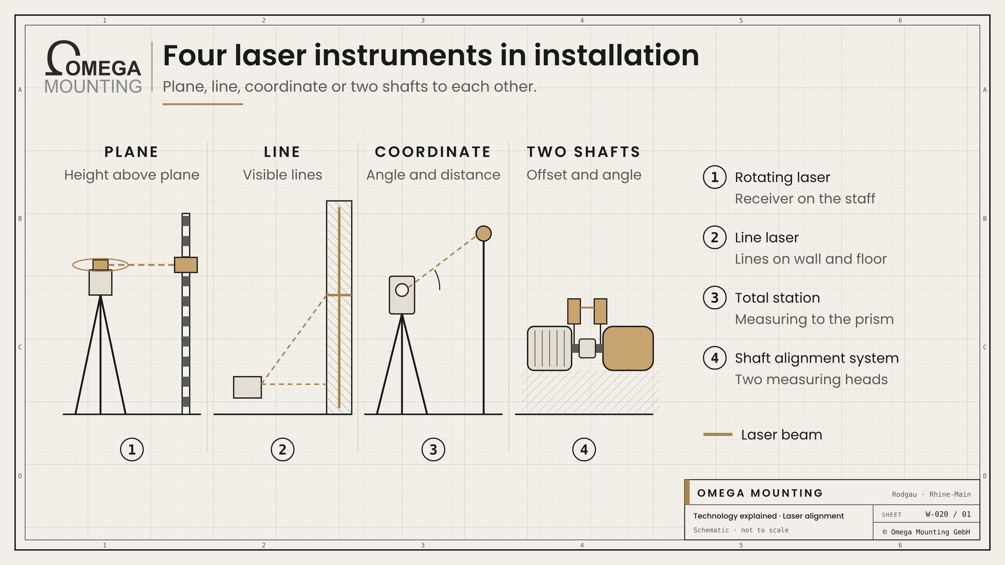
| Instrument | What it measures | Typical use | Limit |
|---|---|---|---|
| Rotating laser | A rotating beam sets up a plane; a receiver on the staff shows the height | Levelling base plates, columns and crane runway height; setting out foundations | Gives height but no position on plan; an unstable set-up falsifies every point |
| Line laser | Projects visible horizontal and vertical lines onto floor, wall and component | Marking out positions, lining up cabinet rows, setting brackets to height | Short range, hard to see in bright light |
| Total station | Measures angle and distance to a prism and calculates coordinates in space | Crane runways over their full length, large halls, setting out gridlines | Needs trained staff and data processing; often a job for a surveyor |
| Laser shaft alignment system | Two measuring heads on two shafts measure offset and angle as they rotate | Aligning motor and pump, gearbox or fan at the coupling | Only for shafts; does not replace levelling the machine itself |
Precision spirit levels, tape measures, feeler gauges and dial gauges stay in use alongside. They measure where the laser cannot reach and serve as a check.
What is laser shaft alignment?
Laser shaft alignment is an application of its own: it does not align a machine in the room but two shafts connected by a coupling. Motor and pump, motor and gearbox, drive and fan must be positioned so that both shafts form one common axis of rotation.
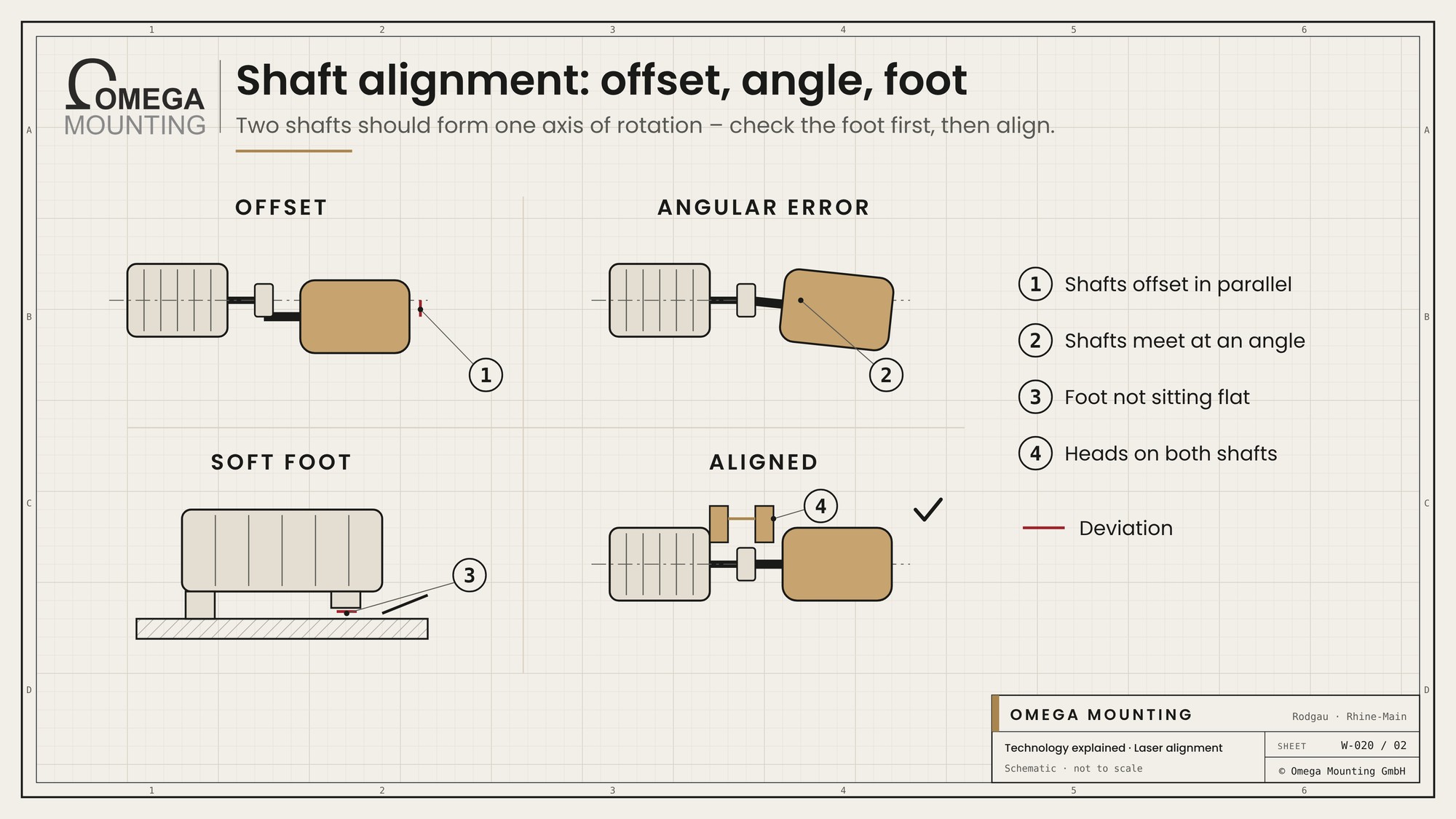
Two errors are possible, often at the same time. With offset misalignment the shafts are parallel but side by side or one above the other. With angular misalignment they meet at an angle. The coupling feels both on every revolution – as heat, vibration and premature wear on bearings and seals.
The alignment system has one measuring head on each shaft. As both are turned together, it records the deviation and calculates how much shimming or lateral movement is needed at which machine foot. Before that we check for soft foot. If the machine does not sit firmly on all its feet, it distorts when tightened down and every measurement is worthless.
How does a laser alignment job run?
A laser alignment job runs in five steps: set the reference, measure, record, correct and re-measure.
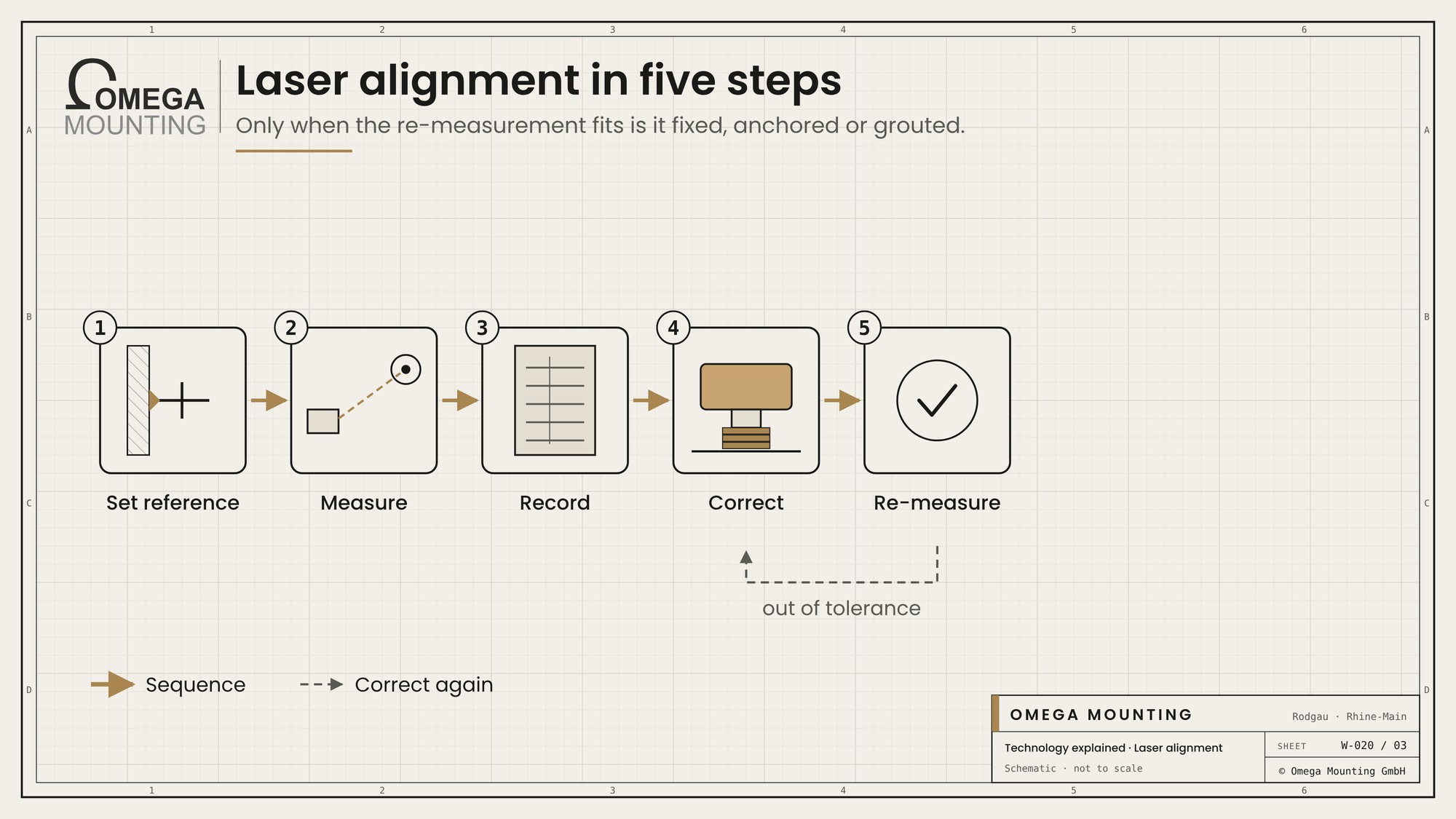
- Set the reference. We agree with the designer or operator which point, which axis and which height apply, and mark them permanently.
- Measure. The laser stands still and the measuring points are taken one after the other – on a crane runway on both sides opposite each other, in a cabinet row at every position.
- Record. Every point gets target, actual and deviation. Without a record, the measurement is lost as soon as the laser is packed away.
- Correct. Corrections are made with shims, adjusting screws, wedges or lateral movement – depending on the component.
- Re-measure. After every correction we measure again at the same point with the same method. Only then is the component fixed, anchored or grouted.
The tolerance being measured against is set beforehand. For machines, the manufacturer gives it in the installation drawing; for crane runways, the crane manufacturer and the crane runway guideline. We work to these values and write the source into the record. How a machine is then fixed permanently is explained in our guide Aligning and anchoring a machine.
What we pay attention to
With laser alignment, the discipline around the measurement matters more than the instrument. This is what we pay attention to:
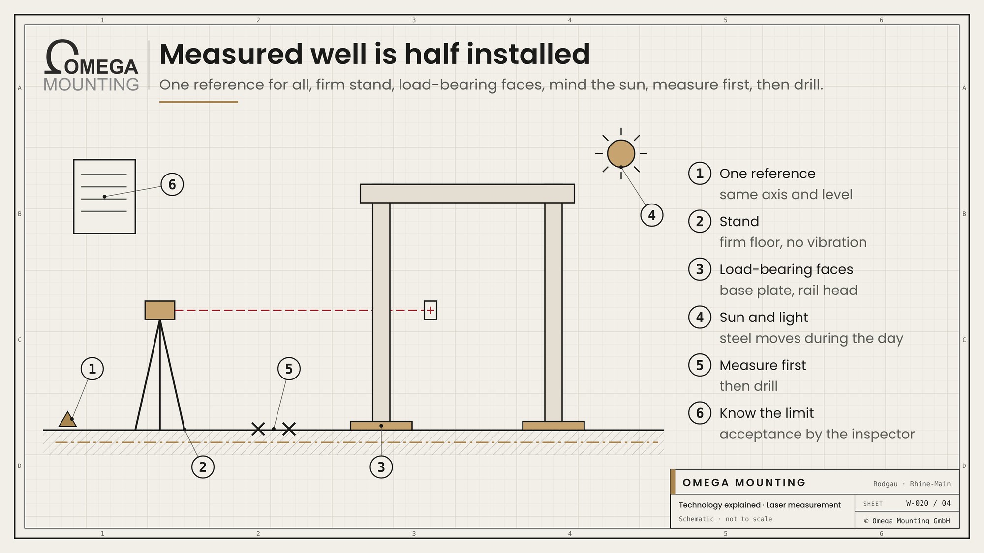
- One reference for all trades. Steelwork, electrical and installation teams measure from the same axis and the same height. Two reference systems in one hall are a typical source of error.
- Set-up before reading. The tripod stands on solid ground, not next to running machines or on vibrating platforms. Every time the laser is moved, we re-check a known point.
- Measure on load-bearing surfaces. We measure on base plates, rail heads or machined surfaces – never on cladding, sheet metal or paint.
- Watch temperature and light. Sun on a steel structure changes its position over the day, and layers of warm air deflect the beam. We schedule critical measurements for quiet periods.
- Measure first, then drill. Set-down positions are marked before the first component is in place. Once something is anchored or grouted, it can no longer be moved.
- Know the limits of mechanical work. We measure and align. Acceptance and inspection stay with the inspector and approved expert, and changes to the structure with the structural engineer.
Where we use it
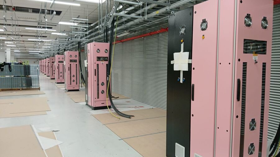
Laser alignment is the first step in many of our installations. In a data center, six Lift & Shift technicians set up 160 power distribution cabinets in eight data halls, 20 cabinets per hall in two rows of 10. Beforehand, every hall was laser-surveyed and every set-down position marked on the floor protection, so that each cabinet stands exactly under its cable outlet and in line with its row – see our report on the PDC installation in a data center. Our project diary entry Installing a crane runway for an overhead crane describes how we brought the columns to the same height with a large rotating laser, checked the diagonals and aligned the runway to gauge by laser. What we offer when installing plant is set out on our page Industrial installation.
More technology explained
Technology explained
Why gauge, height and lateral position of the runway decide the service life of the crane.
Technology explained
A crane whose pillar has to stand plumb on its foundation.
Guide
The guide with all measured values for the crane runway, the procedure and the measurement record.
Do you have questions about how this works on your site?
Questions about how this works on your site – whether your crane runway is still in gauge, or exactly where the new row of cabinets goes? We look at reference points, ground and drawings on site and tell you what needs measuring. The quickest way is a callback.
Free, no-obligation callback
About the author
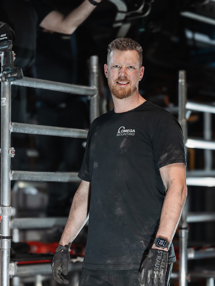
Tobias Schott
Managing director of Omega Mounting GmbH, Rodgau · more than 20 years of hands-on experience in installation and maintenance
A trained mechatronics technician, working in maintenance, servicing and industrial installation since 2004 – first alongside his father, and with Omega Mounting since 2012: from overhead conveyors in Frankfurt to the crane system in a new-build hall. He plans and leads lifting operations as an appointed person (AP) in data centers and on industrial sites in the Rhine-Main region, trains and examines operators of cranes, mobile elevating work platforms and telehandlers, and is a qualified occupational safety specialist. On jobs abroad he is known as the “German Troubleshooter” – the person you call when a site gets stuck. He learned what quality means from his father, not from a manual: Made in Germany as a standard for his own work, not a label. That is why quality comes first at Omega Mounting – ahead of speed and price. The Technology explained articles cover the equipment and techniques his team uses every day: what counts on site is in them – what only appears in the brochure is not.
 English
 German