
- Guide – Maintenance
EMS conductor rail: current collectors, carbon brushes and contact burn
By Tobias Schott · Reading time approx. 22 minutes · As of: November 2026
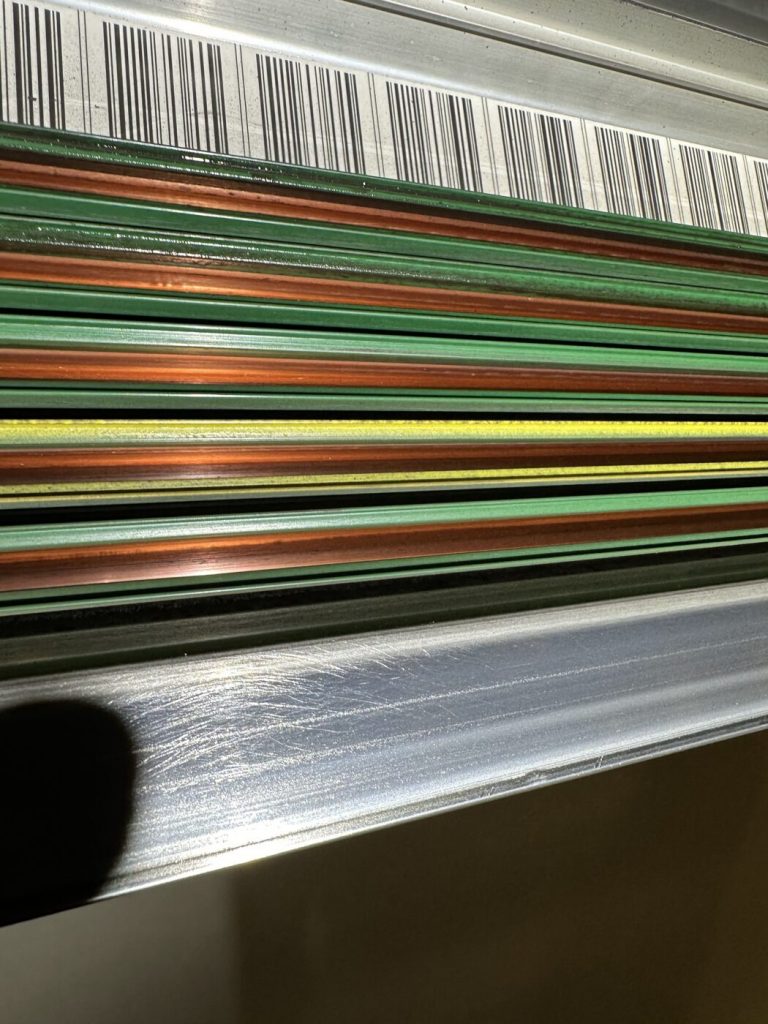
The EMS conductor rail is the lifeline of every electrified monorail: through it the vehicles receive their power and usually their data too. If deposits build up on the contact tracks, dropouts, data errors and in the worst case a contact burn follow. Anyone who knows the causes cleans in a planned way in the isolated state, maintains the current collectors and fixes the mechanical faults behind many “electrical” faults.
An electrified monorail stops, runs on, stops again. The controls report communication errors, here one time, there the next. The electrics are checked, the software reloaded, and after a few days everything is as before. Often the cause is not in the controls. It is up below the hall ceiling: in the conductor rail along which the current collectors of every vehicle glide.
This guide goes into depth on one component. It explains the structure of the conductor rail, the interaction of current collector and carbon brush and how deposits and wear develop. It shows why this becomes a fire risk, how cleaning and subsequent maintenance are done – and who does what. The overview of all assemblies is given in our guide to Overhead conveyor maintenance. Whether to clean, readjust or replace a conductor rail is answered in the guide on Wear on the electrified monorail.
We are a maintenance contractor from Rodgau near Frankfurt. On the conductor rail we clean, adjust mechanically and replace mechanical parts – always in the isolated state. Isolation and electrical measurements are handled by a qualified electrician, from our team on request; data bus and controls belong with the manufacturer.
Key points at a glance
- The conductor rail is the power rail of the electrified monorail: copper contact tracks in insulating profiles, from which current collectors with carbon brushes pick up power and often data.
- Deposits form when carbon abrasion combines with dust, oil, moisture or sugary hall air. This grows into a layer that conducts poorly.
- The consequences range from dropouts and data bus faults through sparks and local heat to contact burn.
- Many faults look electrical but have mechanical causes: offset rail transitions, misadjusted switches, weak springs, worn guide rollers.
- Cleaning is done only on the isolated and secured line, section by section, with extraction instead of blowing out.
- After cleaning, carbon brushes, spring pressure, current collectors, brackets and transitions are checked and repaired mechanically.
- Isolation, voltage drop and insulation measurement and the release for switching back on are handled by the qualified electrician, data bus and controls by the manufacturer.
What is an EMS conductor rail – and what does it carry?
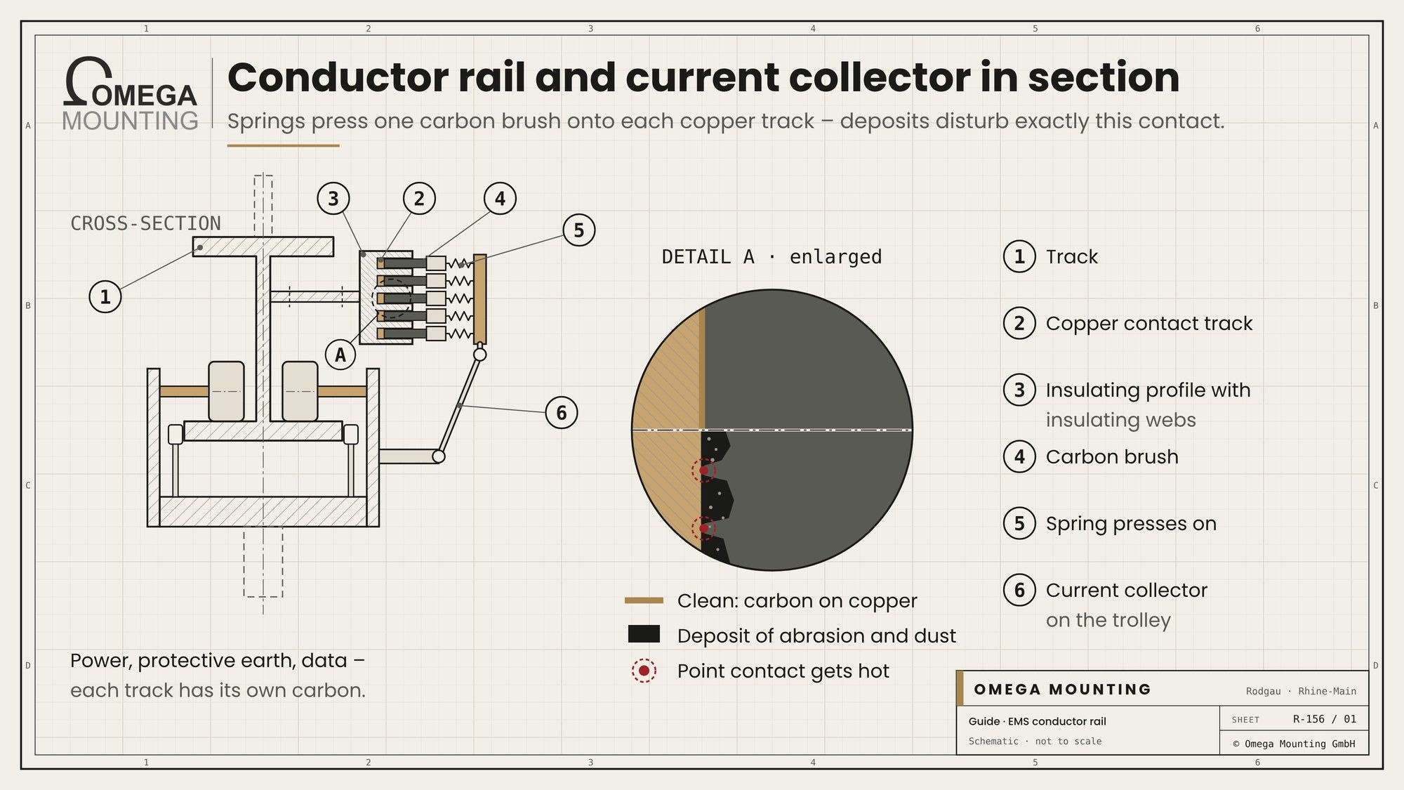
An EMS conductor rail is the power rail along the track of an electrified monorail. It consists of copper contact tracks in insulating profiles, from which the current collectors of each vehicle pick up power and usually control data via carbon brushes.
The electrified monorail is a discontinuous conveyor. Each vehicle runs individually, stops at stations, waits in buffer sections and is diverted via switches. For this, every vehicle continuously needs power for drive and hoist and commands from the controls. Both come not via a cable but via contact. How the system as a whole is built and runs is explained in our knowledge article on the electrified monorail.
Contact tracks and insulating profile
The contact tracks are copper conductors. They sit in a profile of insulating plastic that separates the conductors from each other and protects against contact. Insulating webs between the tracks keep the distance. The conductor rail hangs on brackets parallel to the track, depending on the design at the side of the rail profile or in a chamber of its own.
Power, protective earth and data
An EMS power rail has several conductors. They carry the power for drive and hoist, the protective earth and on many systems separate tracks for control signals or a data bus. If contact on a data track fails even briefly, the vehicle loses its connection to the controls. It stops, even though it could run mechanically.
Feed points, isolating points and transitions
The conductor rail is fed in sections. At isolating points, switches and rail joints it is divided or interrupted. Exactly there the current collector must glide cleanly from one section into the next. Entry funnels at the ends help the carbon over the gap. Feed points, isolating points and protective measures are planned and tested by the qualified electrician.
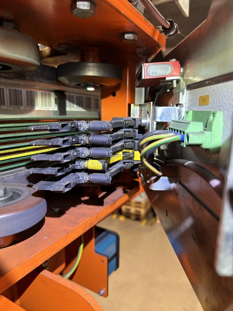
How many conductors there are depends on the system. Simple systems manage with a few conductors. Larger systems carry the yellow-green protective earth and several control and data conductors besides the power. Each copper conductor sits in its own insulating profile; the profiles sit side by side in the chamber or on brackets. The order is mirrored on the current collector. If an insulating profile sits twisted or offset after a repair, the collector runs on the edge instead of the contact track.
Watch for heat at the feed point. There the conductors are connected with cables. Discoloured insulation, deformed plastic or a loose connection indicate heating. This is often noticed first during a mechanical walk. Checking and retightening, however, belongs to the qualified electrician. We report the finding with photo and location and only continue work on this section after release.
How do current collectors and carbon brushes work together?

The current collector sits on the trolley and presses one carbon brush onto each contact track with spring force. This keeps contact even in curves, at joints and at switches – as long as carbon, spring, guidance and conductor rail match.
Carbon brushes as a wearing part
Carbon brushes are deliberately softer than copper. They wear away so that the contact track is spared. This produces abrasion: fine, conductive carbon dust. That is normal and planned for. It only becomes a problem when it does not stay where it falls but combines with other substances. Every carbon has a wear limit given by the manufacturer.
Spring pressure of the current collector
The spring is the most inconspicuous part of the EMS current collector – and one of the most important. If it is too weak, the carbon lifts off at joints, contact jumps and it sparks. If it is too strong, carbon and track wear faster and more abrasion is produced. The correct spring pressure is set by the manufacturer. Over the years the spring force decreases, often unnoticed.
Guidance and joints
The current collector follows the conductor rail via swing arms and joints. Worn joints or a bent arm cause the carbon to sit at an angle. Then only one edge carries and contact gets worse. The contact pattern of the carbon reliably reveals this later.
Data contacts
Data tracks have their own carbons or contacts. They are particularly sensitive, because even a tiny interruption is enough for a communication error. On an electrified monorail in Frankfurt we found wear not only on current collectors but also on data contacts – because vehicles and current collectors were no longer guided cleanly.
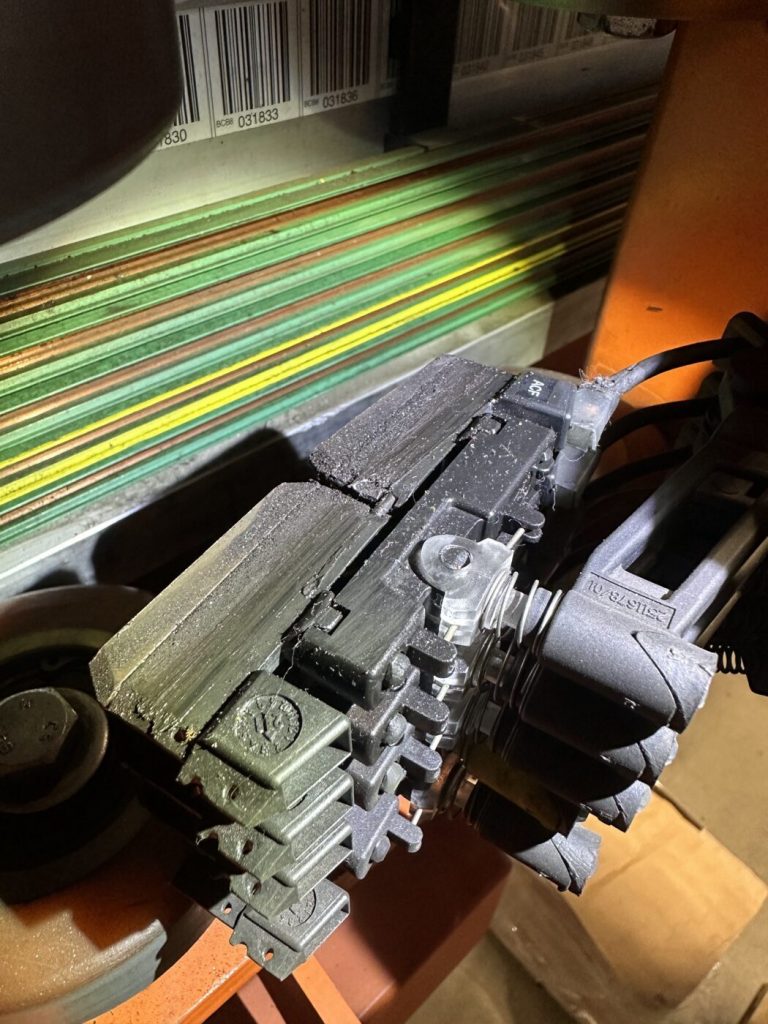
One spring arm per conductor. Many current collectors sit in a housing on the trolley. For each conductor there is a separate arm with a carbon brush, pressed against the contact track by a spring. The arms lie one above the other like the conductors in the chamber. Each arm must move freely and run centrally on its track. A sticking joint, a weak spring or a bent arm is enough for a single conductor to lose contact – often exactly a data conductor.
Checking at the housing. In the isolated state, move each arm individually by hand. It should move easily and spring back by itself. Compare the carbons with each other: if one carbon wears noticeably faster than its neighbours, the cause lies on exactly this track. Also watch the connecting cable at the housing. It moves with every run and must not chafe.
How do deposits and wear develop on the EMS conductor rail?
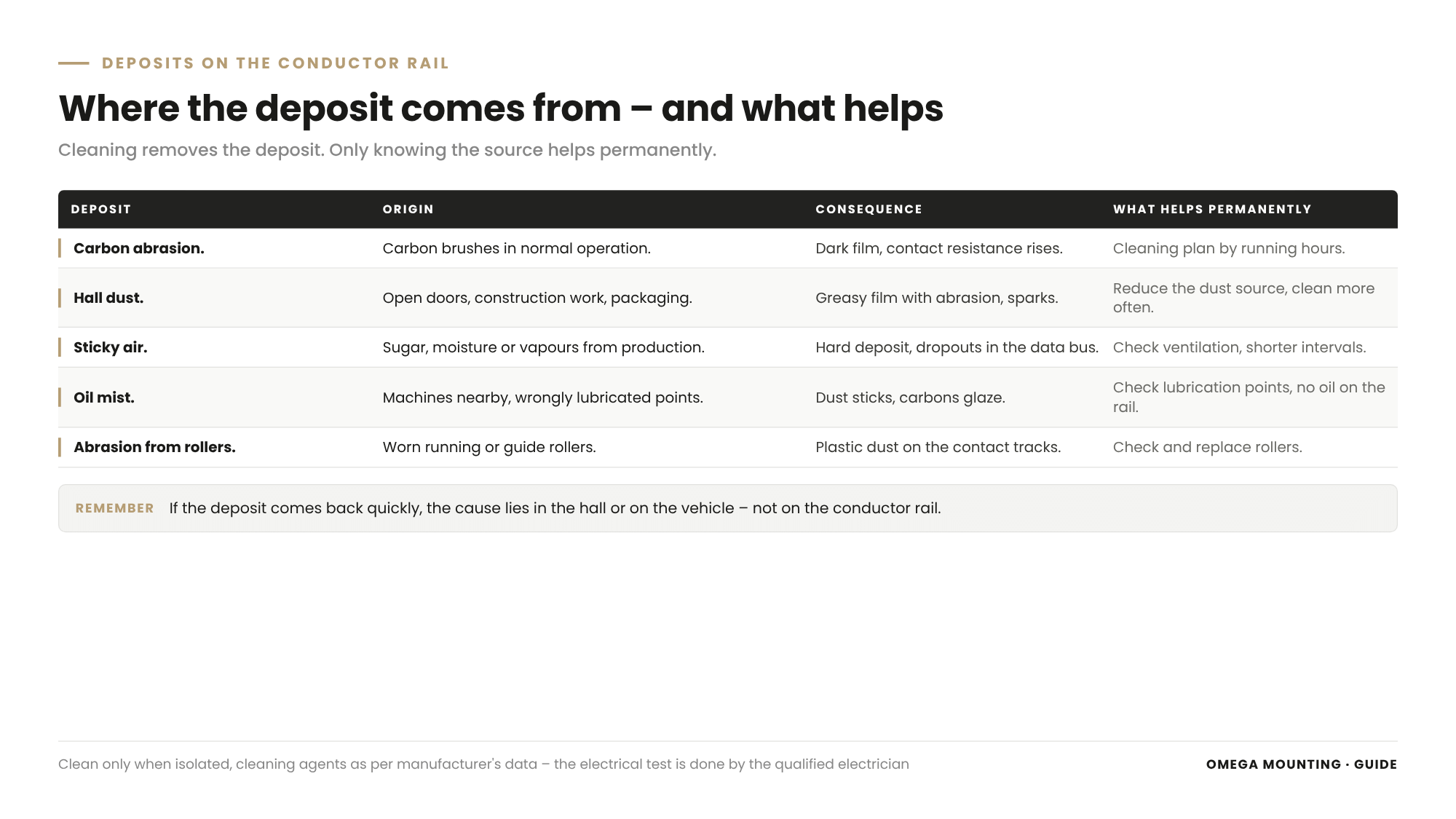
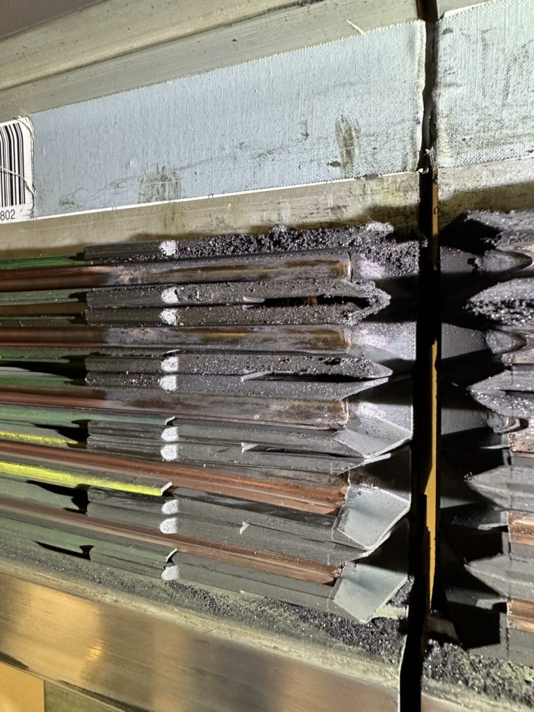
Deposits on the EMS conductor rail form when carbon abrasion combines with what the hall air brings: dust, oil and grease mist, moisture or sugary aerosols. A layer grows on the contact tracks that conducts poorly and disturbs the contact.
What the hall brings
- Dust from production, packaging and traffic in the hall.
- Oil and grease mist from machining, lubrication and drives.
- Moisture and condensate, where warm, humid air meets cooler components.
- Sugar and other sticky aerosols in beverage, juice and food plants.
- Abrasion from the running rollers, which collects under and next to the rail.
How dust becomes an insulating layer
It often starts with a sticky film. Sugary or oily air deposits it on rail and conductor rail. Dust and carbon abrasion settle on it. With every pass the current collectors press the layer on more firmly, local heat bakes it on. In the end there is a hard, dark intermediate layer between carbon and copper. In a juice plant the conductor rail had literally become gummed up over the years.
Wear of the contact track
The copper itself wears much more slowly than the carbon. It wears mainly at the most frequently travelled spots: in front of stations, in buffer sections, at transitions. Typical are scores, burn marks and burrs at joints. When a track needs readjusting or replacing is covered in the guide on wear on the electrified monorail.
Why the problem creeps up
Deposits grow over a long time. At first there are rare dropouts that nobody attributes to a component. Then there are more, and operations get used to restarts. By the time the faults finally attract attention, the layer often covers the whole track.
From deposit to contact burn: dropouts, sparks, fire risk

Deposits increase the contact resistance between carbon and copper. The result is first dropouts and data errors, then sparks and local heat – and with combustible deposits a real fire risk up to contact burn.
Contact resistance: the core of the problem
Current only flows where carbon and copper really touch. Deposits reduce these contact points. The resistance at the contact point rises, and there energy is converted into heat. Along the track the voltage reaching the vehicle drops. Whether and where this happens is measured by the qualified electrician via the voltage drop.
Dropouts and communication errors
If power is missing, the drive jerks, the vehicle stops or restarts. If data contact is missing, telegrams are lost. The controls report an error and stop the vehicle for safety reasons. Such EMS dropouts often occur at the same spots. This clustering is a valuable clue.
Sparks and local heat
If the carbon jumps over a deposit or a burr, small arcs occur. They burn craters into copper and carbon. The surface becomes rougher, abrasion and deposits grow faster. This creates a cycle that reinforces itself without intervention.
Contact burn: a risk to take seriously
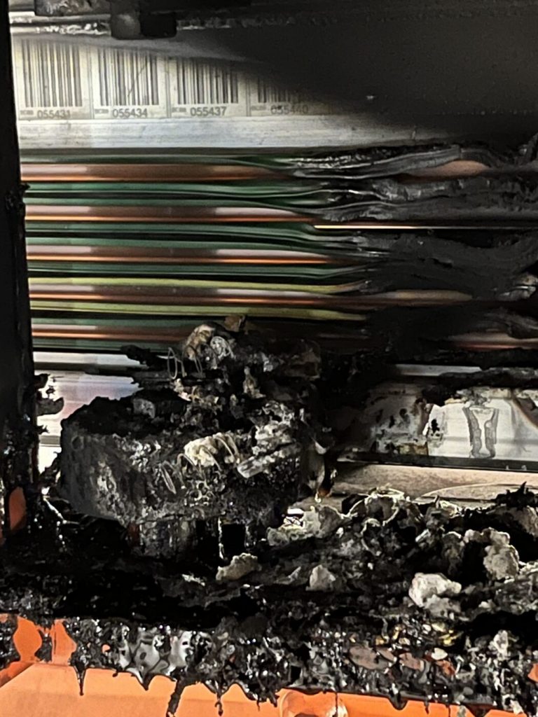
Deposits of sugar, oil and dust can burn. If local heat meets combustible deposits, they can smoulder or ignite. This is called a contact burn on the conductor rail. In a juice plant we found charred residue in the conductor rail – a warning shot that ended lightly.
This is no reason to panic. But it is a clear signal: a soiled conductor rail is not a cosmetic flaw but a fire risk. With cleaning, maintenance and a fixed place in the maintenance plan it is well under control.
If you smell burning, see smoke or scorch marks, your plant's emergency procedure applies. The line is shut down, and a qualified electrician checks the conductor rail before it is switched back on.
Why do faults look electrical when the cause is mechanical?
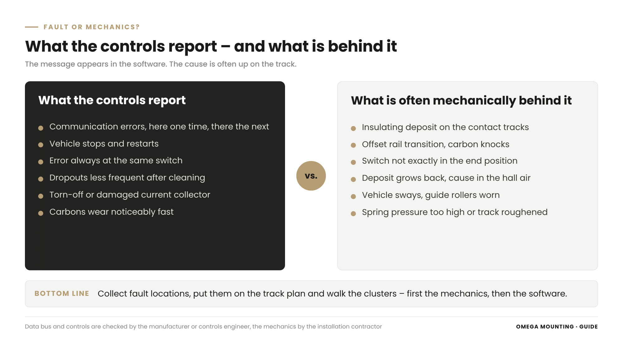
The controls only report that contact is missing – not why. The reason often lies in the mechanics: offset rail transitions, switches without an exact end position, weak springs, worn guide rollers or a soiled track.
An EMS data bus fault is therefore often looked for in the software first. That is understandable, because that is where the message appears. But anyone who only checks the controls is treating the symptom.
Offset rail transitions
If the rails do not line up at a joint, the conductor rail usually does not line up either. The current collector knocks against the edge at every pass. The carbon breaks out, contact jumps. Poorly aligned transitions are mechanical poison for the collectors. How joints are checked and aligned is described in our guide to the electrified monorail track, which we refer to at the end.
Switches without an exact end position
At the switch, the current collector changes to the conductor rail of the moving rail section. If the switch is not exactly in its end position, an offset occurs. The result is communication faults at exactly this spot. How switch shoes, pins and end positions are adjusted is in the guide to the EMS switch.
Trolley and guide rollers
Worn guide rollers let the vehicle sway in the track. The current collector tilts, the carbons run on one side. In Frankfurt exactly this led to increased wear on collectors, drive rollers and data contacts. The current collector is only as well guided as the vehicle it hangs on.
Do not only look for the fault where it is reported
The controls show where a vehicle has stopped. That is not always where the cause is. Collect the fault locations over a while and put them on the track plan. Clusters at transitions, switches or isolating points are the spots for the next walk. How to get systematically from the message to the cause is shown in our guide to troubleshooting on conveyor systems.
Cleaning the conductor rail: isolated, section by section

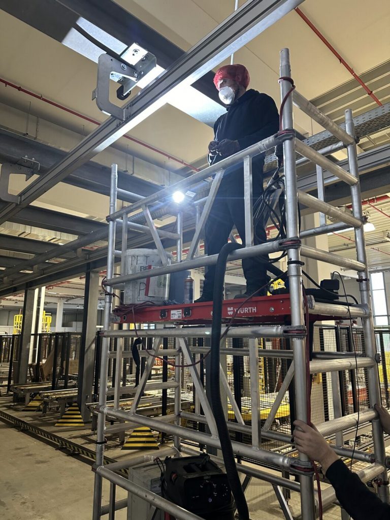
Cleaning a conductor rail means: only on the isolated line secured against switching back on, section by section from height. Deposits are loosened with a suitable cleaner and extracted, transitions and switches are included, and switching back on only happens after drying and release.
Isolation is a job for the qualified electrician
Before the first brush, a qualified electrician isolates the line. They verify the absence of voltage and secure against switching back on. The operator releases the area. The key to the lock stays with those working up top. An emergency stop is not isolation. How the procedure is organised is described in our guide to Lockout tagout in maintenance.
Access at height
The conductor rail hangs below the ceiling, often above machines and walkways. Work is done from a mobile tower or a mobile elevating work platform, with good lighting and a cordoned-off area below. What matters with platforms is shown in our guide to MEWPs in installation work. A very long track is planned like a construction site: sections, sequence, team and material.
Cleaning without causing damage
The cleaning agent follows the data of the conductor rail manufacturer. It must not attack the insulating profile or leave conductive or sticky residue. Encrusted deposits are loosened mechanically without removing copper. Loosened dirt is extracted. Blowing out with compressed air is the worst choice: it spreads conductive dust into profiles, onto insulating webs and into the hall.
Do not forget the insulating webs
Deposits on the insulating webs are more than dirt. Conductive dust can form tracking paths between the conductors there. Whether insulation is still in order is assessed by the qualified electrician after cleaning. For the installation contractor this means: clean the webs as thoroughly as the contact tracks.
Not just the conductor rail
Anyone who only cleans the conductor rail soon gets the deposit back from next door. In the juice plant we therefore cleaned rails, conductor rails, every switch, every transition and also the production surroundings. The current collectors of the vehicles belong to it too, because the same deposit sits on them.
Before switching back on
Cleaned sections dry completely. Tools and material are collected, the cordoning off stays until everything is done. Then the qualified electrician tests and releases the line. Only then does the test run follow.
After cleaning: maintaining current collectors, carbon brushes and transitions
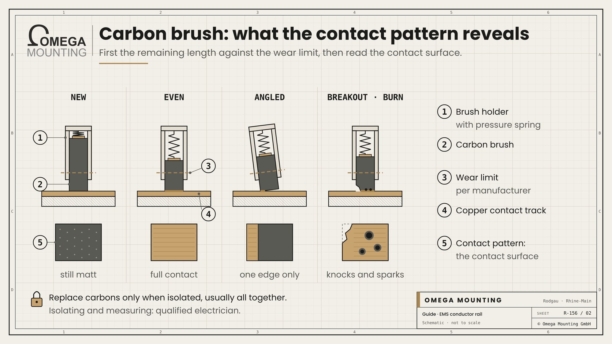
Only after cleaning does the condition of the conductor rail become visible. Now remaining length and contact pattern of the carbon brushes, spring pressure and mechanics of the current collectors, insulating webs, brackets and transitions are checked and repaired mechanically. The electrical measurements follow by the qualified electrician.
Carbon brushes: remaining length and contact pattern
First check the remaining length of each carbon against the manufacturer's wear limit. Then the contact pattern counts. An evenly carrying surface shows healthy contact. If only one edge carries, the current collector is at an angle. Breakouts indicate knocks at transitions, burn marks indicate sparks. Anyone who has to change carbon brushes replaces them in the isolated state and according to the manufacturer's data, usually all carbons of a current collector together.
Spring pressure and current collector mechanics
Spring pressure is checked with a suitable measuring device according to the manufacturer's data. Weak springs are replaced. Joints must move freely without wobbling. Arms should be straight and firmly bolted. Damaged or torn-off collectors are replaced mechanically. The electrical connections on the current collector are disconnected and reconnected by our own qualified electricians.
Contact tracks, insulating profiles and brackets
After cleaning, scores, burn marks and burrs at joints become visible. Insulating profiles are inspected for cracks and heat deformation. Brackets must be tight and guide the conductor rail parallel to the rail. We align loose brackets mechanically, in coordination with the qualified electrician. Conductor rail sections, feed points and isolating points are replaced by the qualified electrician or manufacturer.
Transitions and switches
Now a second look at the spots where the carbons have suffered pays off. Do rail and conductor rail line up at every joint? Are the entry funnels at isolating points and switches seated correctly? In the juice plant some switches and rail transitions were not set correctly. That caused additional communication faults that cleaning alone would not have fixed.
The electrical test
Voltage drop along the track, insulation resistance, protective earth and data transmission are tested by the qualified electrician, manufacturer or controls engineer. Ideally, mechanical findings and measurement results are brought together in one list. The check points that have proven themselves in practice are in our overhead conveyor maintenance checklist.
Who does what on the EMS conductor rail?

On the EMS conductor rail, the installation contractor cleans, adjusts mechanically and replaces mechanical parts. The qualified electrician isolates, measures, tests and releases. Manufacturer and controls engineer are responsible for data bus, controls and specifications, the operator for the risk assessment.
Installation contractor
The installation contractor cleans conductor rail, rail, switches and current collectors in the isolated state. They replace carbon brushes, springs and mechanical parts of the current collectors. They align rail transitions, switches and brackets. And they document what they have found – with location, photo and finding.
Qualified electrician
Work on electrical installations may only be carried out by qualified electricians or persons under their direction and supervision. This is laid down in the German accident prevention regulation for electrical installations and equipment (DGUV Regulation 3). On the conductor rail this means: isolation, verifying absence of voltage, measurements, feed points, isolating points and the release for switching back on lie with the qualified electrician.
Manufacturer and controls engineer
The manufacturer specifies wear limits, spring pressure and suitable cleaning agents. They supply carbons, current collectors and conductor rail parts. Data bus, controls, parameters and software stay with the manufacturer or controls engineer.
Operator
The operator remains responsible. The German Ordinance on Industrial Safety and Health (BetrSichV) requires them to set the type, scope and intervals of inspections of their work equipment in the risk assessment. They release work and name contacts. This classification is practical guidance and not legal advice. What your plant needs follows from your risk assessment.
Symptom, cause, measure: the conductor rail overview
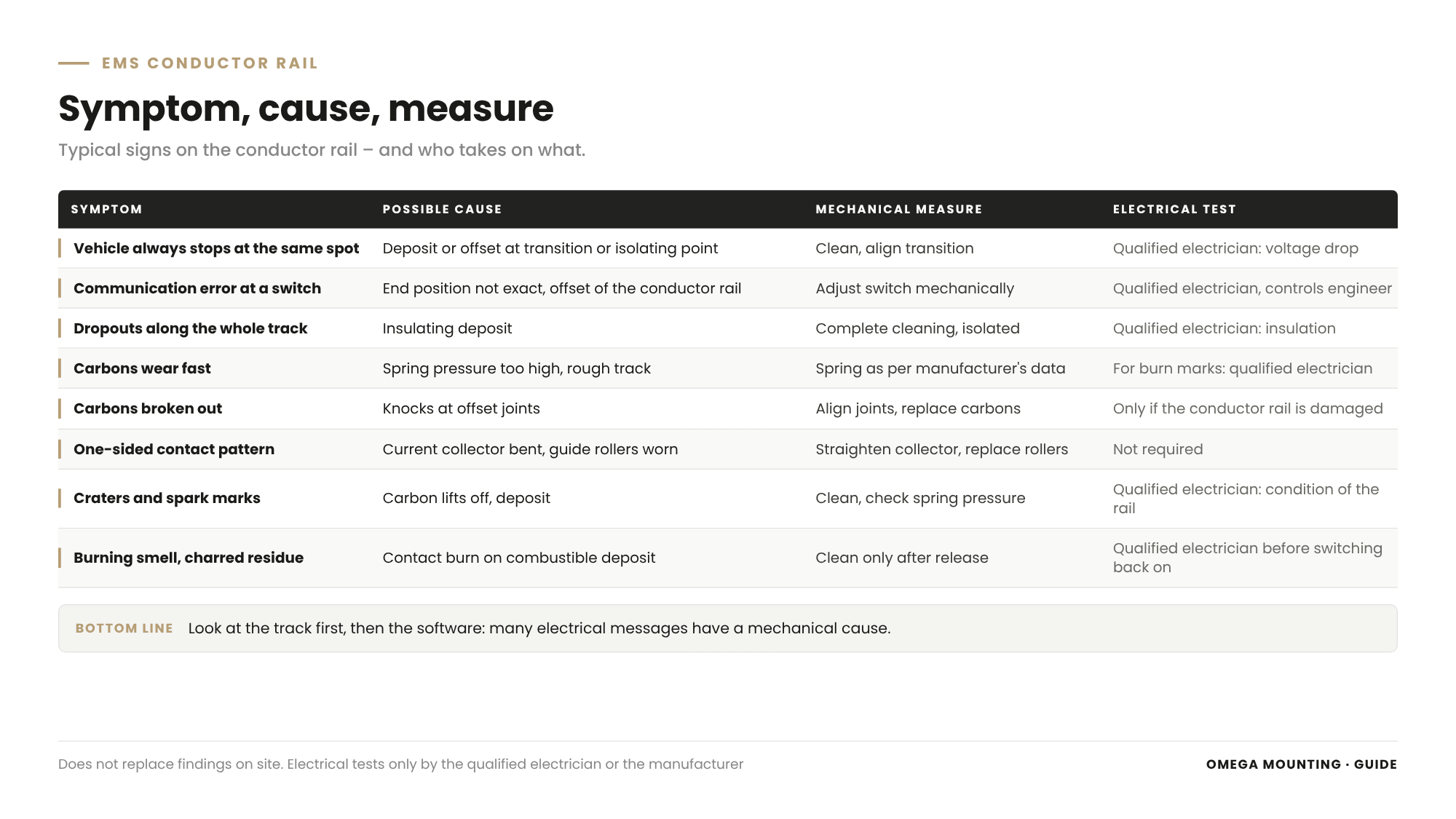
The overview assigns typical symptoms on the conductor rail to possible causes. It shows which mechanical measure the installation contractor takes on and who tests electrically.
| Symptom | Possible cause | Mechanical measure | Electrical test by |
|---|---|---|---|
| Vehicle always stops at the same spot | Deposit or offset at transition or isolating point | Clean, align transition | Qualified electrician: voltage drop |
| Communication error at a switch | End position not exact, offset of the conductor rail | Adjust switch mechanically | Qualified electrician, controls engineer: data transmission |
| Dropouts along the whole track | Insulating deposit on the contact tracks | Complete cleaning in the isolated state | Qualified electrician: insulation, voltage drop |
| Carbons wear noticeably fast | Spring pressure too high, rough track | Spring as per manufacturer's data, check track | Qualified electrician for burn marks |
| Carbons broken out | Knocks at offset joints | Align joints, replace carbons | Not required as long as the conductor rail is undamaged |
| One-sided contact pattern | Current collector bent, guide rollers worn | Straighten or replace current collector, replace rollers | Not required |
| Craters and spark marks on the copper | Carbon lifting off, deposit | Clean, check spring pressure | Qualified electrician: condition of the conductor rail |
| Lots of carbon dust below the track | High abrasion, contact pressure, rough track | Clean, check spring pressure | Not required |
| Burning smell, charred residue | Contact burn on combustible deposit | Clean only after release | Qualified electrician before switching back on |
The table does not replace findings on site. But it helps to ask the right questions before anyone searches the software.
Typical mistakes on the EMS conductor rail

The typical mistakes on the EMS conductor rail are troubleshooting only in the controls, blowing out instead of extracting, working without isolation, replacing carbons without looking at the transitions and cleaning that has no fixed place in the maintenance plan.
- Software instead of track. The controls are reloaded, the deposit remains. After a short time the dropouts come back.
- Blowing out with compressed air. The dust is not gone afterwards but spread – in profiles, on insulating webs and in the hall.
- Working without isolation. A live conductor rail is not cleaned, not even “just briefly”.
- Only replacing carbons. The new carbons break out at the same offset joint as the old ones.
- Wrong cleaner. The agent attacks the insulating profile or leaves a film on which new deposits settle faster.
- Switching on too early. Damp sections or missing release by the qualified electrician turn the cleaning into a new risk.
- Wiping away burn marks. Charred residue is removed, but nobody asks why it burned there.
- Cleaning as a one-off action. The conductor rail is cleaned thoroughly once and then forgotten again.
The mistake behind the mistakes
Behind almost all mistakes is the same assumption: the conductor rail is electrics, so the electricians take care of it. In fact, mechanics, cleanliness and electrics meet here. Only when the installation contractor and the qualified electrician look at the track together do the dropouts disappear for good. How operators report warning signs early is described in our guide on Spotting wear on machines.
EMS conductor rail in the Rhine-Main region: how we work
We clean and maintain conductor rails on electrified monorails in production plants in the Rhine-Main region and beyond – from Rodgau in Frankfurt, Offenbach, Hanau, Darmstadt and Aschaffenburg, usually at weekends or during company holidays.
Our core is mechanics and cleaning; isolation as well as disconnecting and reconnecting are handled on request by our own qualified electricians. We clean conductor rail, rail, switches and current collectors in the isolated state. We check carbon brushes, springs and current collectors, replace mechanical parts and align transitions, switches and brackets. We bring mobile towers, extraction, lighting and a well-rehearsed team.
Isolation according to your procedure, connections and electrical measurements on the conductor rail are handled by our own qualified electricians. The feed from the building stays with your electricians, data bus and controls with the manufacturer or controls engineer. We coordinate with everyone in advance so that isolation, cleaning, testing and restart fit into one weekend. The full scope of our Maintenance and servicing work is set out on our service page. For EMS maintenance in the Rhine-Main region, the short distances from Rodgau are an advantage when an appointment is postponed at short notice.
Project examples
Two jobs show what matters on the conductor rail: deposits as the cause of dropouts and fire risk, and mechanical wear as the cause of unclean power and data transmission.
Juice plant: gummed-up conductor rail, dropouts and a warning shot
In a juice plant the electrified monorail had constant dropouts and data bus faults. The cause was in the air: sugary, humid air from production laid a sticky film on rails and conductor rails. Dust settled on it. This created an insulating layer of dirt with contact resistances, sparks and local heat. The system had already had a contact burn; charred residue bore witness to it.
We cleaned the complete, very long track section by section from the mobile tower, with a larger team, industrial cleaner and extraction. Rails, conductor rails, every switch and every transition were included, plus the production surroundings. Maintenance followed: switches and rail transitions were partly not set correctly and were corrected mechanically. We serviced current collectors, carbons and contacts. The electrical tests were carried out by the qualified electrician.
For your system this means: cleaning and mechanical adjustment belong together. Anyone who only cleans keeps the faults at the misadjusted switches.
Frankfurt: wear on current collectors and data contacts
With the maintenance of an overhead monorail system in Frankfurt we found a very old system. Vehicles and current collectors were no longer guided cleanly through the rails. This led to increased wear on collectors, drive rollers and data bus contacts, partly to damaged or torn-off current collectors and to interrupted data transmission. Rail transitions were partly no longer in line.
We replaced guide and running rollers, renewed switch shoes and pins, aligned transitions and checked the power and data contact areas. The result was more reliable power and data transmission.
For your system this means: anyone who only replaces torn-off current collectors without straightening guidance and transitions will soon be replacing them again.
Does your electrified monorail have dropouts or a soiled conductor rail?
Then get in touch with us. Send us photos of the conductor rail, the current collectors and the spots where vehicles stop. We will tell you what we take on mechanically and electrically and where the handover point to your electricians lies.
What this means for your role
For buyers: Separate cleaning and mechanical maintenance from the electrical test in the order. Ask who isolates, who measures and who releases again. Clear service boundaries prevent gaps at the weekend.
For designers: The accessibility of the conductor rail decides the effort of every cleaning. Plan space for a mobile tower or platform and think of the hall air: where there is sugar, oil or moisture in the air, the conductor rail needs more care.
For project managers and site managers: You bring the qualified electrician, installation contractor and production together. As project manager you set sections, sequence and restart. As site manager you coordinate isolation, cordoning off and release on site.
For maintenance managers: Collect fault locations and put them on the track plan. Give conductor rail maintenance a place of its own in the maintenance plan, with cleaning, carbon checks and coordination with the qualified electrician.
For warehouse and logistics managers: Your people see the dropouts first. Give them a reporting route with location and vehicle. And always take a burning smell or scorch marks seriously.
For operations and plant managers: Dropouts cost cycle time, a contact burn can cost more. Release the windows that cleaning and maintenance need, and require findings with a release.
Conductor rail cleaning and maintenance plan: template on request
The conductor rail cleaning and maintenance plan is a one-page working document for your electrified monorail. It guides you through preparation, isolation and release, cleaning, maintenance afterwards and switching back on. Each point has fields for “responsible”, “done” and “finding” or “open”. There are deliberately no intervals or number fields – those belong to your system and your hall air. Request the template via our contact form – keyword “Conductor rail cleaning and maintenance plan”.
Why Omega Mounting?
We are based in Rodgau near Frankfurt, can be reached around the clock and work with our own fitters, our own equipment for work at height and our own workshop. We know electrified monorails from maintenance: we have cleaned gummed-up conductor rails, adjusted switches and transitions and serviced current collectors. We say beforehand where our service ends: the plant electrics are done by our own qualified electricians, the building electrics by your electricians, the controls by the manufacturer. What this means for you: a single point of contact for cleaning, mechanics and plant electrics, who agrees the handover point with you in advance.
Conclusion
The EMS conductor rail decides whether power and data arrive cleanly at the vehicle. Deposits of carbon abrasion and hall air increase the contact resistance and lead to dropouts, sparks and in the worst case contact burn. Many faults have mechanical causes at transitions, switches, springs and guide rollers. Cleaning is done only when isolated, then carbons, current collectors and transitions are maintained, and the qualified electrician tests and releases. If your system has dropouts, send us photos and the fault locations – we will get back to you with an honest assessment.
Planning a move-in, installation or maintenance in the Rhine-Main region?
Tell us briefly what you need – we'll come back with an honest assessment.
Free, no-obligation callback
You may also be interested in these guides
Maintenance & Servicing
Maintenance & Servicing
Maintenance & Servicing
About the author
Tobias Schott
Managing director of Omega Mounting GmbH, Rodgau · more than 20 years of hands-on experience in installation and maintenance
A trained mechatronics technician, working in maintenance, servicing and industrial installation since 2004 – first alongside his father, and with Omega Mounting since 2012: from overhead conveyors in Frankfurt to the crane system in a new-build hall. He plans and leads lifting operations as an appointed person (AP) in data centers and on industrial sites in the Rhine-Main region, trains and examines operators of cranes, mobile elevating work platforms and telehandlers, and is a qualified occupational safety specialist. On jobs abroad he is known as the “German Troubleshooter” – the person you call when a site gets stuck. He learned what quality means from his father, not from a manual: Made in Germany as a standard for his own work, not a label. That is why quality comes first at Omega Mounting – ahead of speed and price. He writes these guides from that practice: what works on our sites is in them – what exists only on paper is not.
Frequently asked questions
Often it is the conductor rail. Deposits of carbon abrasion, dust, oil or sugary air increase the contact resistance, and the contact for power or data jumps. Add to that mechanical causes such as offset rail transitions, misadjusted switches, weak springs or worn guide rollers. The controls then report an error, but not its cause.
The EMS conductor rail is the power rail along the track of an electrified monorail. Copper contact tracks in insulating profiles carry power, protective earth and often data. The current collectors of the vehicles pick them up via spring-loaded carbon brushes.
Deposits reduce the contact points between carbon and copper. At the contact point energy is converted into heat, sparks and local heat occur. If the deposit is combustible, for example of sugar, oil and dust, it can smoulder or ignite. With cleaning and maintenance this risk is well under control.
Only on the isolated and secured line. Section by section, the deposit is loosened from height with a cleaner as per manufacturer's data and extracted, not blown out. Insulating webs, transitions, switches and current collectors are included. Switching back on only happens after drying and release by the qualified electrician.
At the latest when the manufacturer's wear limit is reached. Breakouts, burn marks or a one-sided contact pattern are also reasons to look more closely. Then not only the carbon is replaced but the cause is looked for too, such as an offset joint or a bent current collector.
Isolation, measurements and all work on live parts are handled by a qualified electrician. Cleaning, replacing carbons and mechanical adjustment can be carried out by an installation contractor in the isolated state. Data bus and controls stay with the manufacturer or controls engineer.
Yes. If the rail does not line up at the joint, the conductor rail usually does not line up either. The current collector knocks, the carbon jumps, and contact on the data track is briefly lost. The same happens at switches that are not exactly in their end position.
That depends on hall air, operation and manufacturer specification. In plants with sugar, oil or a lot of dust in the air the conductor rail needs considerably more care than in a clean assembly hall. The operator sets this in their risk assessment and maintenance plan.
Send us photos of the conductor rail and the current collectors, the spots where vehicles stop and details of the hall air. We will then look at the track on site and tell you what we take on mechanically and electrically and where the handover point to your electricians lies. Your contact is Tobias Schott – reachable via our contact form.
 English
 German