
- Guide – Maintenance
EMS switch: setting switch shoes, pins and end positions correctly
By Tobias Schott · Reading time approx. 23 minutes · Updated: November 2026
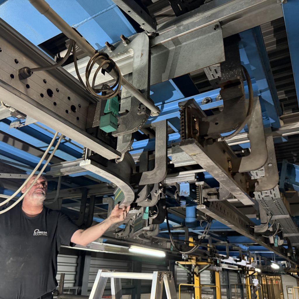
An EMS switch decides whether a vehicle turns off cleanly or stops. Every vehicle runs over it, and its end position must sit precisely with every switching action. Worn switch shoes, worn-out pins and a wandering end position show up as a knock, a stop or a data error. Anyone who knows the mechanics of the switch finds the cause – and knows where the qualified electrician takes over.
The EMS switch is the moving heart of an electrified monorail. It changes the route many times in every shift, often for long periods without a break. If it fails, not one vehicle stops but a whole line. And because it hangs below the hall ceiling, hardly anyone sees how it slowly wears.
This guide goes into depth on one component: the switch. It explains structure, damage patterns, inspection, adjustment and replacement – and how a misadjusted switch puts strain on rollers, collectors and data bus. The overview of all assemblies is given in our guide to Overhead conveyor maintenance. How the system runs as a whole is explained in our knowledge article on the electrified monorail.
We are a maintenance contractor from Rodgau near Frankfurt. We dismantle switches, replace switch shoes and pins, set end positions mechanically and align transitions. Limit switches and switch motors are connected by our own qualified electricians; controls and parameters stay with the manufacturer. We say so in every chapter.
Key points at a glance
- An EMS switch is a moving rail section with switch drive, switch shoes, pins, end positions, locking and end position sensing.
- It is the weak point of the track, because every vehicle runs over it and every switching action moves the mechanics.
- Typical damage includes worn switch shoes, worn-out pins, wandering end positions, knocking transitions and mechanically decommissioned switches.
- The installation contractor takes on the mechanics: drive, shoes, pins, stops and alignment. Limit switches, sensors and switch motors are handled by our own qualified electricians, controls and parameters by the manufacturer.
- Adjustment follows a fixed sequence: isolate, record findings, replace wearing parts, set end positions, line up the transition, test runs.
- A misadjusted switch does not only harm itself. It knocks on running rollers, current collectors and carbon brushes and can trigger communication faults.
- Decommissioned switches can often be put back into service – after repair, a function test and release by the operator.
What is an EMS switch – and how is it built?

An EMS switch is a moving section of the track that diverts the vehicles of an electrified monorail from one route to another. A drive moves it into the end position, a locking device holds it there, and sensors report to the controls that the switch is in a safe position.
The electrified monorail is a discontinuous conveyor. Each vehicle runs individually and is sent on its way via switches. Only the switches turn a line into a network of lines, branches and buffer sections.
Designs: sliding switch and turntable switch
The design depends on the manufacturer and the age of the system. In a sliding switch, the drive moves a frame with several rail sections across the direction of travel. It stops as soon as the right section is in front of the fixed track. In a turntable switch, a rail section turns about a pivot and thus connects the routes. For maintenance, the same applies to every design: what moves, what guides, what fixes the end position?
The components of a switch
- Moving rail section: straight or curved, with running surfaces for running and guide rollers and usually with a section of the conductor rail.
- Switch drive: a motor with gearbox and a mechanism of crank, lever or spindle that moves the moving part.
- Switch shoes: guide and sliding pieces in which the moving part runs. They hold it in position sideways and in height. Depending on the manufacturer they are also called sliding shoes or guide pieces.
- Pin: pivots and joints between drive, levers and moving part, often mounted in bushes.
- Stops and locking: they fix the end position mechanically and hold the switch there while a vehicle runs over it.
- End position sensing: limit switches or proximity sensors report to the controls that the end position has been reached.
The mechanics extend to the sensor bracket. The sensor itself, its wiring and its switching point are electrics.
Why is the switch the weak point of every electrified monorail?

The switch is the weak point of every electrified monorail because movement, impact and precision meet there: every vehicle runs over it, every switching action moves drive, shoes and pins, and even a small offset in the end position becomes a knock at every pass.
Every vehicle runs over it
If the whole fleet runs through a branch, this section sees more passes than almost any other point of the system. Add to that lateral forces when the vehicle enters the curve. The guide rollers then press against the moving part and try to push it out of position.
Transitions that move
The switch has a transition to the fixed track at entry and at exit. There is a separation joint there over which rollers and current collectors roll. On the fixed track, a rail joint is aligned and stays that way. At the switch, one side of the joint moves with every switching action. How well the transition lines up therefore depends solely on how precisely the end position sits.
The end position must be exact
A fixed rail joint changes slowly. An end position, on the other hand, is approached anew with every switching action. If shoes, pins or stops wear, it wanders. At first the offset is barely visible. Then you hear it as a knock at every pass. Finally the end position sensing no longer reports reliably, and the vehicle stops in front of the switch.
Then there is age: for older switches the manufacturer does not always still supply parts. Then people improvise, and some switches are eventually locked.
What damage does a worn EMS switch show?
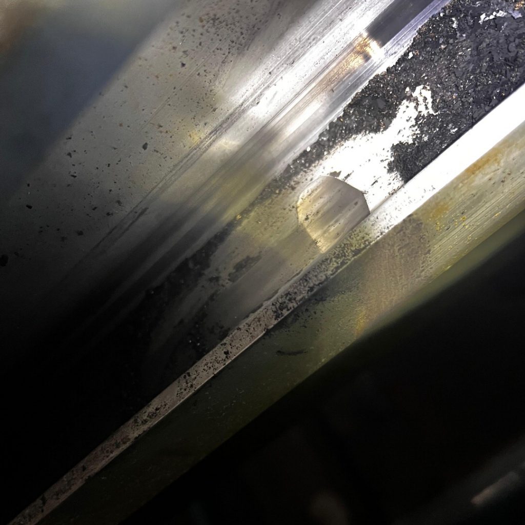
A worn EMS switch shows worn switch shoes, worn-out pins and bushes, a wandering end position or one that is no longer reported, knocking transitions with wear marks, loose stops, damaged brackets and, in the extreme case, a switch that has been mechanically decommissioned.
Worn switch shoes
The shoes guide the moving part with every switching action. Over time they wear away. Then the moving part has play. It no longer sits precisely in the end position but slightly askew or too low. Typical signs are shiny wear tracks, abrasion below the switch and audible rattling when switching.
Worn-out pins
Pins in drive and levers run in bushes that are often barely lubricated. Both wear, the joint gets play, and the play of all joints adds up. In the end the drive covers its travel correctly, but the moving part no longer arrives precisely where it should.
Wandering end position
A wandering end position is usually a consequence, not a cause. Shoes, pins or stops have given way, or someone has adjusted a stop to bridge a fault. The results are offset, knocks and sensor reporting errors.
Knocking transitions
A knocking transition is the damage pattern operators hear first. The rollers run over an edge instead of rolling over a smooth joint. Over time they knock wear marks into the running surface there. Around the switch you see this in scored running surfaces, abrasion and broken rollers.
Brackets, suspension and stops
Knocks and vibrations are transmitted to the brackets below the building structure. Typical are loose bolts, cracks at welds and torn-off brackets. Whether the building structure can carry the loads is assessed by a structural engineer.
Mechanically decommissioned switches
The last damage pattern is an emergency solution: a switch that was locked in one end position after damage. The system keeps running, but one route is missing.
Mechanics or electrics: who is responsible for what at the switch?

At the switch, the installation contractor takes on the mechanics: switch drive mechanically, switch shoes, pins, stops, locking, alignment of the transitions and brackets. Limit switches, proximity sensors, switch motor and conductor rail are handled at our company by our own qualified electricians, controls and parameters by the manufacturer.
Switches are the assembly where mechanics and electrics come closest together. That is why a clear boundary is particularly important here.
What is mechanical
- Switch drive as mechanics: gearbox, coupling, lever, crank or spindle, fixing.
- Switch shoes, pins and bushes: check play, replace, secure.
- Stops and locking: set the mechanical end position.
- Transitions and brackets: line up, align, repair after approval.
What is electrics, sensors and controls
- Limit switches and proximity sensors: switching point, wiring, end position sensing.
- Switch motor electrically, controls and data bus.
- Conductor rail in the switch area: measurements, insulation, absence of voltage.
Limit switches, proximity sensors, switch motor and measurements on the conductor rail are handled by our own qualified electricians. Controls, data bus and parameters stay with the manufacturer or controls engineer. Isolation and securing follow your procedure before we touch the switch. How the procedure is set up is described in our guide to lockout tagout in maintenance.
Where both work together
The end position has a mechanical and an electrical side. We set the stop so that the switch lines up precisely. The qualified electrician then sets the switching point of the end position sensing to it. If only one side is adjusted, the switch is not right. It lines up but does not report. Or it reports but does not line up – and that is the more dangerous case.
How do you inspect a switch mechanically?

You inspect a switch mechanically in a fixed sequence: first in operation with ears and eyes from the hall floor, then isolated by hand at drive, shoes, pins and stops, finally with the straightedge at the transition – tolerances as per manufacturer's data.
In operation: listen and look
Watch several switching actions from the hall floor. Does the switch rattle, does it jerk? Is there a knock when a vehicle runs over the transition? Is there abrasion below the switch – plastic from rollers, black dust from carbon brushes, metal chips? Note which switch stands out and in which switching direction.
Isolated: touch
Once the line is isolated and secured, check from the working platform. Move the moving part in the end position by hand. Noticeable play in height or side points to shoes or pins. Check the joints individually, the stops for seating and the welds on brackets for cracks.
At the transition: line up
Place a rule or straightedge over the transition between fixed track and moving part. Check the running surface and the guide surface. You see immediately whether there is an edge or everything lines up. Check each end position, because often only one switching direction lines up. How much deviation is permissible is set by the manufacturer.
What the controls reveal
The fault memory shows at which switch end position signals are missing or vehicles stop. Have it read out by the qualified electrician or controls engineer – the list is the best starting point for the mechanical inspection. How to get from the fault message to the cause is shown in our guide to troubleshooting on conveyor systems.
Documenting
Record the findings per switch with photos. This list determines the order of the repair. Check points for the whole system are in our overhead conveyor maintenance checklist.
Positioning strip and read head at the switch. On many systems the barcode strip also runs over the moving section. Check whether it continues at both transitions without gap or edge. If the moving part is only slightly offset in the end position, the read head briefly loses the track. The vehicle then stops in front of or in the switch, even though it has switched mechanically. Anyone who only checks the controls here is looking in the wrong place.
Adjusting an EMS switch: setting end positions, lining up the transition, testing

Adjusting an EMS switch means: having the line isolated, recording findings, replacing worn switch shoes and pins, setting the end positions mechanically, lining up the transitions and checking with test runs – the end position sensing is set by the qualified electrician.
Isolating and securing
Before the first touch, the line is isolated according to your procedure – by our or your qualified electrician – and secured against being switched back on. The area below the switch is cordoned off and nearby vehicles are secured.
Wearing parts first, then adjustment
Adjusting an end position on worn shoes does not last. The play carries the adjustment away again in a short time. That is why new switch shoes and pins come first. Adjustment follows.
Setting end positions mechanically
The moving part moves into one end position. We set the stop so that the running surfaces line up in height and side. The locking must engage securely without jamming. Then the remaining end positions follow, on sliding switches with several positions each one individually. Each end position is set and checked on its own.
Lining up the transition
Every transition is checked with the straightedge: running surface, guide surface and, where the design allows, the conductor rail chamber. Where the fixed track before the switch is itself worn, the best switch adjustment does not help. Then the rail section in front of the switch is aligned or shifted slightly so that the end position sits on less worn rail.
End position sensing by the qualified electrician
Once the mechanics are set, the qualified electrician sets the switching point of the limit switches or proximity sensors. They check the signal to the controls. Only then is the line switched back on.
Test runs
The switch switches several times into each end position. Then vehicles run over it in each direction, first empty, then with load. We watch for knocks at the transition, smooth running of the rollers, clearance of the guide rollers and a current collector that glides smoothly over the joint.
Release after the repair
After work that can affect safety, the operator determines whether and how inspection takes place. The basis is their risk assessment under the German Ordinance on Industrial Safety and Health (BetrSichV). The inspection is carried out by a person qualified to inspect. We hand over findings, photos and a list of replaced parts. This section is a practical classification, not legal advice.
Switch shoes and pins: repair or replace?

Switch shoes and pins are usually replaced because they are wearing parts. The parts around them are repaired: mountings, brackets, stops and bearing points. If the manufacturer no longer supplies, parts are re-made to measurement, manufacturer's documents or operator approval.
Replacing switch shoes
The old shoes are removed and compared with a new part. This shows how much has worn away and whether the guide has suffered too. New shoes go into a cleaned guide. Lubrication only if the manufacturer specifies it, because grease binds dust.
Pins and bushes as a pair
A new pin in a worn-out bush soon has play again. Pin and bush are therefore checked together and usually replaced together. The bearing point is cleaned and checked for out-of-roundness. After fitting, the pin is secured. Why pairs wear together is explained in our guide on Wear on the electrified monorail.
When force becomes necessary
A pin that can only be loosened with a hammer, a switch part that jams, a drive that catches: that is a finding, not a work step. Anyone who carries on with force hides the cause. It may be a distorted bracket, a bent guide or a wrongly made seat. We measure before we hit again.
Re-making in the workshop
Older switches often have parts that nobody supplies any more. Then we re-make switch shoes, pins, bushes or brackets in our workshop in Rodgau. The basis is a survey, a manufacturer's drawing or the operator's approval. Materials and characteristic values for load-bearing parts are set by the manufacturer or operator, not by the installation contractor. How to deal with missing parts is described in our guide to spare parts that are no longer available.
Brackets and drive
Torn-off brackets are repositioned and welded if the operator approves. The structural analysis of the suspension is assessed by a structural engineer. On the drive we replace mechanical parts such as coupling and lever. Connecting the motor electrically is done by the qualified electrician.
How a misadjusted switch strains rollers, collectors and data bus

A misadjusted switch strains the whole system: every offset at the transition knocks on running and guide rollers, on current collectors and carbon brushes. Current collection becomes unsteady, and communication faults occur that look like electronics but have a mechanical cause.
The chain of consequential damage
- Rollers: a transition with an edge knocks against the running rollers at every pass. Tyres break out, bearings suffer, the running surface gets scores.
- Guidance: if the moving part is offset sideways, the guide rollers press against the edge. The vehicle jerks and sways.
- Collectors: the conductor rail runs through the switch. If it does not line up at the transition, the current collector jumps. Every offset knocks on collectors and carbons.
- Data: where power and data run via contact, the contact briefly breaks at the offset transition. The controls report a communication error.
What this means for troubleshooting
Do not only look for the fault where it is reported. If data errors accumulate at one spot, check the switch there mechanically. The electrical measurement is done by the qualified electrician. Only both together show the cause of an EMS switch fault. Conversely, a worn track in front of the switch makes even the best switch knock. Switch and track are therefore always assessed together.

Putting decommissioned switches back into service

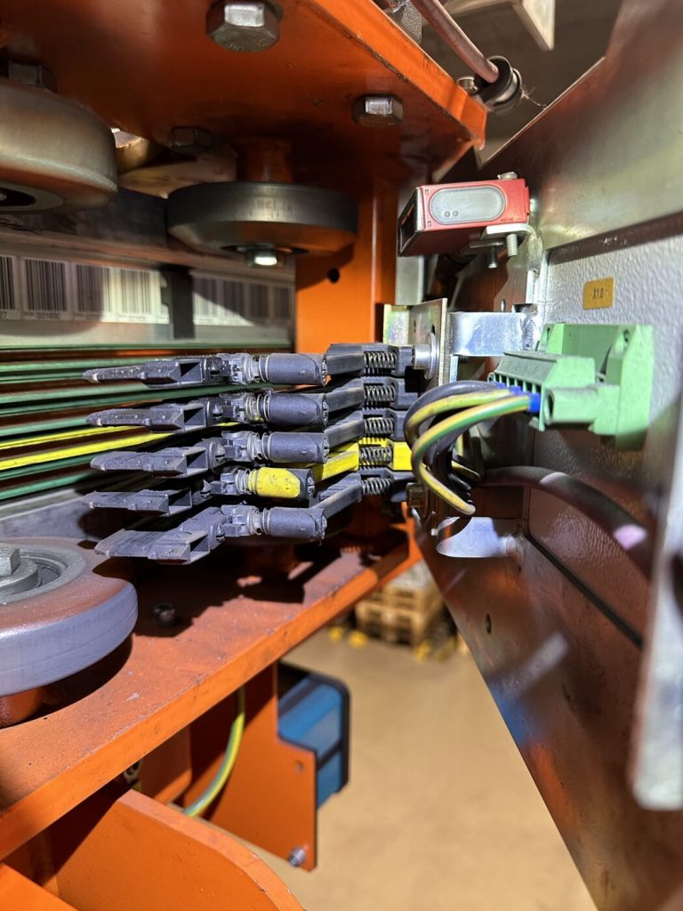
A mechanically decommissioned switch can often be put back into service. Findings are recorded, the cause of the decommissioning is eliminated, wearing parts are replaced, end positions set and transitions lined up. Then the qualified electrician tests the electrics and the operator releases the switch.
Why switches are decommissioned
It usually starts with damage: a broken part or an end position that no longer reports. There is no time or no part for the repair. What was meant as a temporary solution often stays that way for a long time.
What decommissioning costs
Vehicles take detours, buffer sections fill up. If a switch fails elsewhere, there is no alternative route. Availability drops even though everything seems to be running.
The way back
It starts with the question of why the switch was decommissioned and which parts are missing. If they are no longer available, they are re-made to measurement and approval. Then repair, adjustment and function test follow as for any other switch. Important: a switch that has been locked for a long time is often blocked or bypassed in the controls. Whether it goes back into operation is decided by the operator and controls engineer. That belongs in the planning, not at the end of the window.
Many switches in the weekend window: how to plan the work

Many switches in one weekend window succeed if every switch has been assessed and prioritised beforehand, spare parts are ready per area, workplaces at height are prepared, teams work in parallel and the end consists of function test, documentation and release.
Findings and sequence
Before the first window, every switch is documented and assessed. The sequence results from this. Switches that can stop the material flow and badly damaged switches come first. Decommissioned switches follow once the running ones are safe.
Spare parts are ready per area, re-made parts are finished before the window.
Access at height
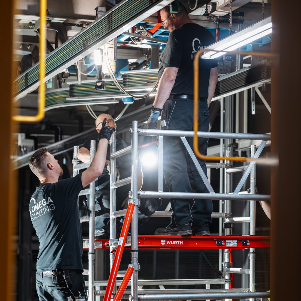
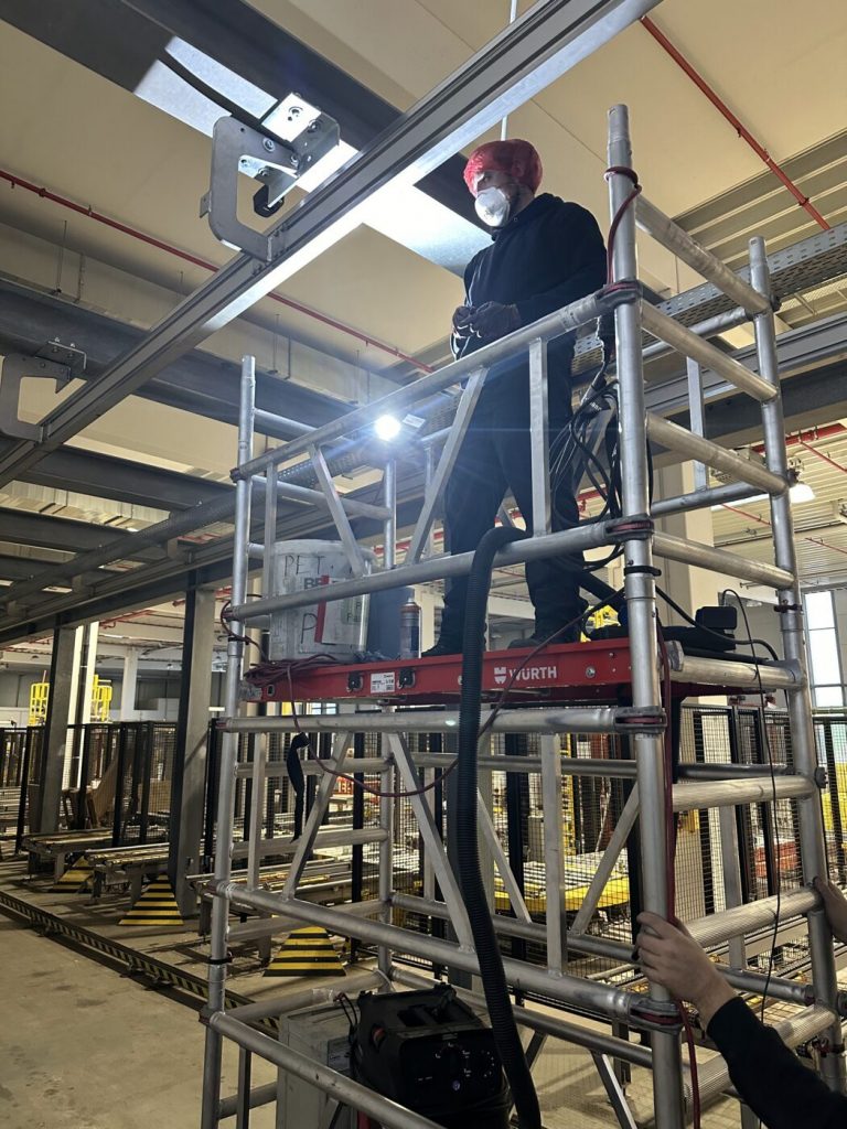
Switches hang below the ceiling, often above production areas. Work is done from mobile working scaffolds or the mobile elevating work platform, with additional lighting and a cordoned-off area below. Tools are secured against falling. What applies when working from the platform is described in our guide to installation work with a MEWP.
Working in parallel
Several technicians work at different switches at the same time, each group in its isolated area. A qualified electrician – from our team or yours – is scheduled for isolating, end position sensing and switching back on.
Fallback and completion
For every switch it is decided in advance what happens if it is not finished by restart. Usually it is locked in a safe end position and completed in the next window. What is possible during operation and what needs a real shutdown window is separated in our guide to Maintenance during live operations. Every window ends with a function test, photos, a record and a list of open points.
Symptom, cause, next inspector: the EMS switch overview

The overview assigns possible mechanical causes to each symptom at the EMS switch and names who checks next: the installation contractor the mechanics, the qualified electrician sensors and electrics, manufacturer or controls engineer controls and data.
| Symptom | Possible mechanical cause | Who checks next |
|---|---|---|
| Rattling when switching | Worn switch shoes, play in pins and levers. | Installation contractor |
| Knock at every pass | Offset at the transition, wandered end position, worn rail. | Installation contractor |
| Switch does not reach the end position | Jamming guide, bent part, stiff drive. | Installation contractor, motor electrically by the qualified electrician. |
| End position is not reported | End position mechanically misadjusted, sensor bracket loose. | Installation contractor, switching point by the qualified electrician. |
| Vehicle stops in front of the switch | Missing end position signal, locking does not engage. | Qualified electrician and installation contractor together. |
| Data error at the switch | Offset of the conductor rail at the transition, jumping current collector. | Installation contractor, measurement by the qualified electrician. |
| Abrasion below the switch | Rollers knock at the transition, shoes wear away. | Installation contractor |
| Crack in the bracket | Knocks, vibration, overload. | Installation contractor, structural analysis by the structural engineer. |
| Switch mechanically locked | Broken part, missing spare part. | Installation contractor, controls by the manufacturer. |
The table does not replace findings on site. But it shows where to start.
Typical mistakes on the EMS switch
The typical mistakes on the EMS switch are: adjusting on worn parts, replacing pins without bushes, checking only one end position, readjusting the limit switch instead of the mechanics, forgetting the rail in front of the switch and decommissioning switches instead of eliminating the cause.
- Adjusted on old shoes. The end position is right on Monday and soon wanders off again.
- Pin replaced, bush left. The joint soon has play again.
- Only one end position checked. The other switching direction keeps knocking.
- Limit switch readjusted instead of the mechanics. The switch reports again but does not line up. The vehicle runs over an edge.
- Rail in front of the switch forgotten. The switch is well adjusted, the transition still knocks because the fixed track is worn.
- Decommissioning as a permanent solution. A route is missing for a long time.
Almost all mistakes have the same root: the switch is seen as a single part. In fact it is a chain of drive, joints, shoes, stops, transitions and sensors. Anyone who fixes only one link shifts the problem to the next.
Switch maintenance in the Rhine-Main region: how we work
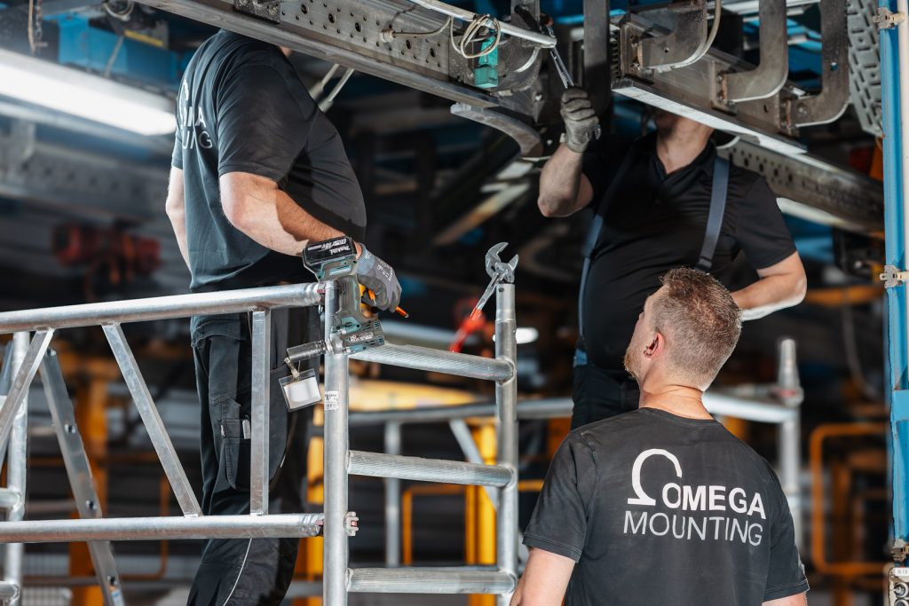
For us, EMS maintenance in the Rhine-Main region means for switches: recording findings mechanically, repairing and adjusting – in Frankfurt, Offenbach, Hanau, Darmstadt and Aschaffenburg and beyond, at weekends and in shutdown windows.
Our core is the mechanics; disconnecting and reconnecting are handled on request by our own qualified electricians. We dismantle switches, replace switch shoes, pins, bushes and rollers, set end positions and align transitions. We weld brackets after approval and re-make missing parts in our own workshop. We bring scaffolding and lighting.
Isolation, limit switches and electrical measurements are handled by our own qualified electricians by arrangement. Controls and parameters stay with the manufacturer or controls engineer. Short distances from Rodgau help with walk-throughs before the window and when a shutdown is postponed. Our scope of services is described on the page Maintenance and servicing.
Project examples
The following jobs show what matters with switches: record findings before the window starts, repair the mechanics completely and always see switches together with rail and conductor rail.
Frankfurt: many switches in weekend shutdowns
With the maintenance of an overhead monorail system in Frankfurt we found a very old system at a manufacturing company in Hesse. It had many switches in several operating areas. We found worn and broken running and guide rollers, scored running surfaces, offset rail transitions and damaged brackets. Some switches had been mechanically decommissioned after parts had broken off.
First every switch was documented and assessed and the sequence agreed with the customer. Work was done at weekends in a tight time window between the end of production and restart, in parallel from mobile towers and mobile platforms.
Rollers were replaced, internal ones partly with complete dismantling of the switch. Switch shoes and pins were replaced and adjusted, transitions aligned, end positions set. Torn-off brackets were welded. Worn rail sections were shifted slightly so that the end positions sit on less worn rail. The decommissioned switches went back into operation.
For your system this means: an old switch does not necessarily need replacing. It needs findings, the right parts and a prepared window.
Beverage plant: switches adjusted after cleaning
In a beverage plant an electrified monorail had constant dropouts and faults in the data bus. Sugary, humid air had covered rails and conductor rail with a sticky deposit. We cleaned the very long track section by section from the mobile tower – every switch and every transition included. The subsequent maintenance showed: switches and transitions were partly not set correctly and caused additional communication faults. Poorly aligned transitions are mechanical poison for the collectors. We adjusted them and serviced current collectors, carbons and contacts. The electrical tests were carried out by the qualified electrician.
For your system this means: anyone who only cleans fixes part of the faults. The switches belong in the same maintenance.
Are switches knocking, jamming or standing still at your plant?
Then get in touch with us. Send us a list of the noticeable switches, photos and, if available, extracts from the fault memory. We will tell you what we take on mechanically and electrically and where the handover point to your electricians lies.
What this means for your role
For buyers: Separate the findings per switch from the repair in the quotation. Require the supplier to name the interface to the qualified electrician.
For designers: Switch position and accessibility decide how much effort every later maintenance takes. Plan space for mobile scaffolds and record the design of every switch in the documents.
For project managers and site managers: Plan the switches as a sequence of windows with findings before and release after. On site you coordinate isolation, scaffolding, cordoning off and the qualified electrician.
For maintenance managers: Your fault memory is the best switch list. Have the most noticeable switches checked mechanically first, before one has to be decommissioned.
For operations and plant managers: Every decommissioned switch costs availability, even if the system is running. Release the windows needed for a complete repair.
EMS switch check sheet: template on request
The EMS switch check sheet is a one-page working document per switch. It guides you through identification and location, observation in operation, mechanics in the isolated state, transitions per end position, responsibility and measure. Each point has fields for “finding”, “responsible” and “done” or “open”. There are deliberately no number fields or tolerances – the manufacturer supplies those. Request the template via our contact form – keyword “EMS switch check sheet”.
Why Omega Mounting?
We are based in Rodgau near Frankfurt, can be reached around the clock and work with our own fitters, our own equipment for work at height and our own workshop. The linked job in Frankfurt shows how we work on switches: every switch assessed, switch shoes and pins replaced, end positions set, decommissioned switches brought back into operation. We say beforehand where our service ends: the electrics at the switch are done by our own qualified electricians, controls and parameters by the manufacturer. What this means for you: a single point of contact for the mechanics and electrics of your switches, who defines the handover point to your electricians in advance.
Conclusion
An EMS switch is the component where an electrified monorail stumbles most often. Worn shoes, pins and end positions cause knocks, stops and data errors. The solution is a fixed sequence: record findings, replace wearing parts, set end positions mechanically, line up transitions, test. The end position sensing is set by the qualified electrician, release is given by the operator. Decommissioned switches can often be brought back. If your switches knock or stand still, send us your switch list and photos – we will get back to you with an honest assessment.
Planning a move-in, installation or maintenance in the Rhine-Main region?
Tell us briefly what you need – we'll come back with an honest assessment.
Free, no-obligation callback
You may also be interested in these guides
Maintenance & Servicing
Maintenance & Servicing
Maintenance & Servicing

About the author
Tobias Schott
Managing director of Omega Mounting GmbH, Rodgau · more than 20 years of hands-on experience in installation and maintenance
A trained mechatronics technician, working in maintenance, servicing and industrial installation since 2004 – first alongside his father, and with Omega Mounting since 2012: from overhead conveyors in Frankfurt to the crane system in a new-build hall. He plans and leads lifting operations as an appointed person (AP) in data centers and on industrial sites in the Rhine-Main region, trains and examines operators of cranes, mobile elevating work platforms and telehandlers, and is a qualified occupational safety specialist. On jobs abroad he is known as the “German Troubleshooter” – the person you call when a site gets stuck. He learned what quality means from his father, not from a manual: Made in Germany as a standard for his own work, not a label. That is why quality comes first at Omega Mounting – ahead of speed and price. He writes these guides from that practice: what works on our sites is in them – what exists only on paper is not.
Frequently asked questions
Usually because of wear on the mechanics: worn switch shoes and worn-out pins create play, the end position wanders, and the end position sensing no longer reports reliably. Add to that jamming guides, bent parts and loose stops. Less often the electrics themselves are the cause – that is checked by the qualified electrician.
In a sliding switch, the drive moves a frame with several rail sections across the direction of travel. In a turntable switch, a rail section turns about a pivot. In both, guides, pins and stops determine the end position.
By rattling when switching, abrasion below the switch and play of the moving part in the end position. In the isolated state the play can be felt by hand. Comparing a removed shoe with a new part shows how much has worn away.
The installation contractor sets the mechanical end position: they set the stops so that the transitions line up. The qualified electrician then sets the switching point of the limit switches or proximity sensors. Only when both sides are right is the end position correctly set.
Yes, if the manufacturer no longer supplies them. The basis is a survey, a manufacturer's drawing or the operator's approval. Materials for load-bearing parts are set by the manufacturer or operator.
Often yes. It is repaired and adjusted, and the qualified electrician tests the electrics. The operator and controls engineer take it back into operation, and the operator releases it.
Because the conductor rail runs through the switch. If it does not line up at the transition, the current collector jumps and the contact briefly breaks. The controls report a communication error – the cause is mechanical.
Whether and how is determined by the operator in their risk assessment. After work that can affect safety, a person qualified to inspect carries out the inspection. For this we hand over findings, photos and the list of replaced parts.
Send us a list of the noticeable switches, photos, the location and, if available, extracts from the fault memory. We will then look at the switches on site and tell you in writing what we take on mechanically and electrically and where the handover point to your electricians lies. Your contact is Tobias Schott – reachable via our contact form.
 English
 German