
- Technology explained – equipment and protection
Load spreading mats: why the ground decides more than the crane
By Tobias Schott · 7-minute read · Updated October 2026
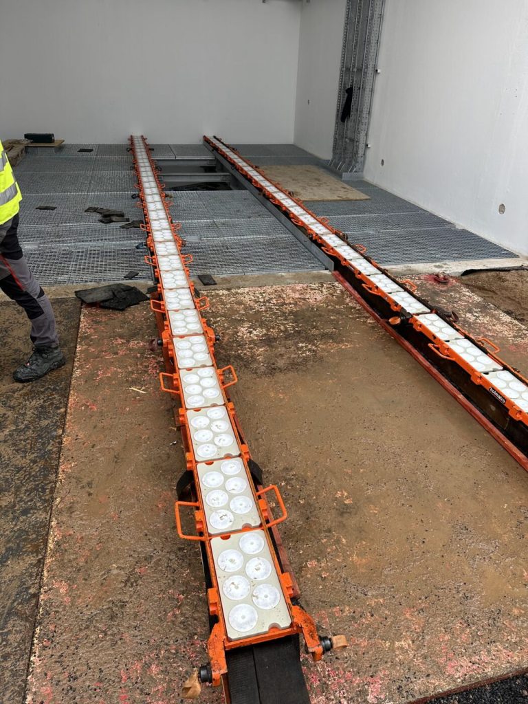
Load spreading mats spread the force of an outrigger, a skate or a bearing point over a larger area – and so decide whether the ground carries a heavy lift or gives way.
Load spreading mats sit under the outriggers of every mobile crane, under MEWPs and on the routes of heavy transports. On site they are called outrigger pads, crane mats, spreader plates or simply “the mats”; the German terms are Lastverteilplatten or Abstützplatten. If you treat them as an accessory, you underestimate them: the crane’s capacity is no use if the ground under one outrigger collapses.
This article explains what ground bearing pressure is, which types of mat exist and where the typical mistakes lie. How to plan floor loads and crane standing areas for your project is covered in our move-in planning guide – we do not repeat it here.
What is a load spreading mat?
A load spreading mat is a stiff plate of steel, aluminium, plastic or timber that spreads a concentrated force over a larger area and so reduces the pressure on the ground. It sits between equipment and ground: under a crane’s outrigger foot, under the wheel of a heavy-duty skate, under the bearing of a skid track.
A point load – a force acting on a very small area – becomes a distributed load. The mat does not make the ground any stronger. It only spreads the load so that the existing ground can take it. Whether that is enough depends on the ratio of force, area and permissible ground bearing pressure.
Key facts
- Purpose: Turn point loads from outriggers, skates and bearings into distributed loads; bring the ground bearing pressure below the permissible value
- Types: Steel plates, aluminium outrigger pads, polyethylene plastic pads, timber mats of joined planks, timber baulks as stacks or packing
- Design parameters: Outrigger force or wheel load of the equipment, area and stiffness of the mat, permissible ground bearing pressure
- Marking: Series-made mats usually carry dimensions, self-weight and permissible load; timber packing and home-made mats have no marking, so their suitability has to be proven another way
- Inspection duty and interval: Visual check before every use; the type and interval of further inspections are set by the employer in the risk assessment under the German Industrial Safety Ordinance (BetrSichV), together with the manufacturer’s data
- Discard criteria: Cracks, permanent deformation, broken edges, split or rotten timber, melted or brittle plastic, illegible marking
Ground bearing pressure: force divided by area
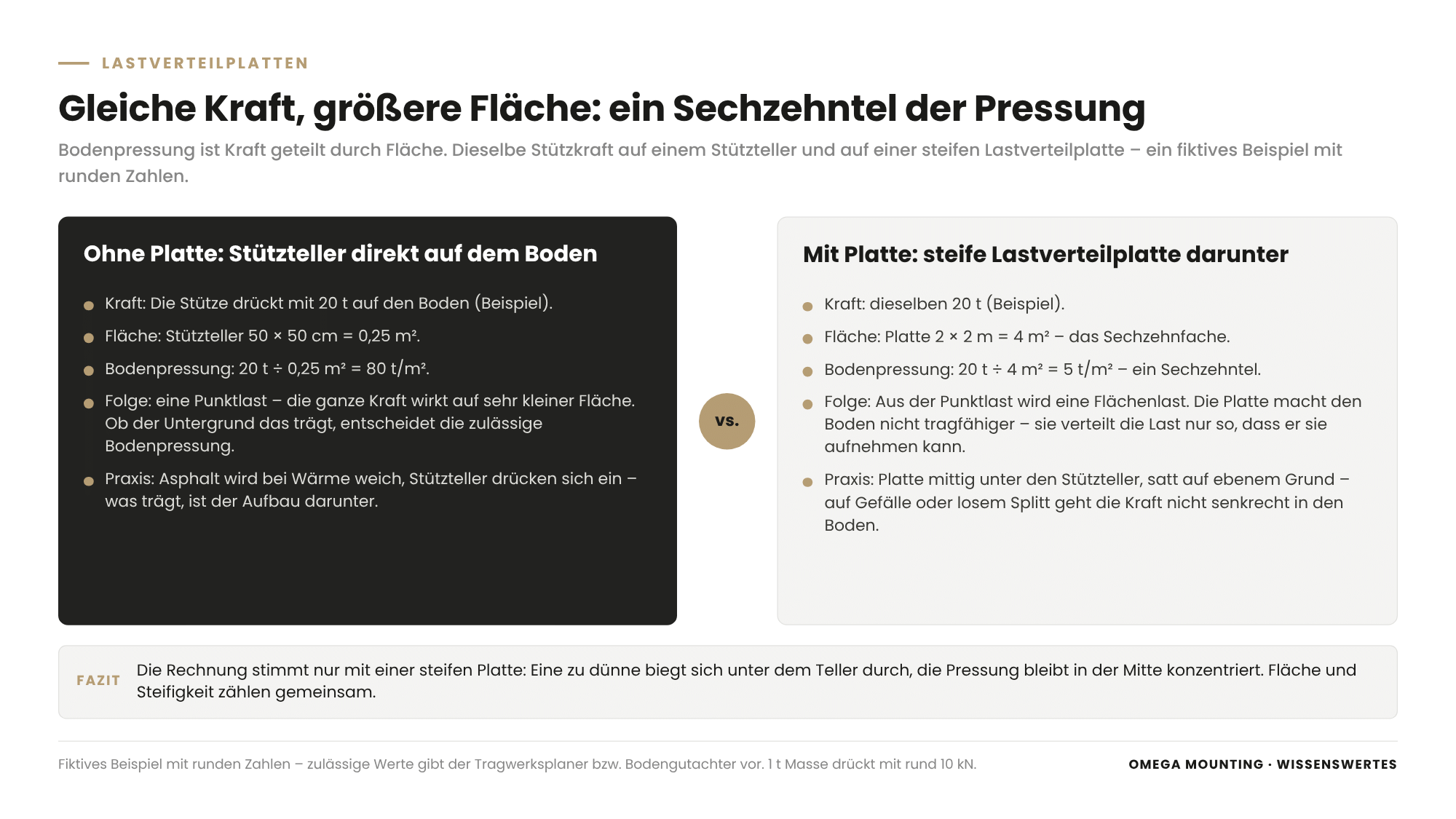
Ground bearing pressure is the force pressing on the ground divided by the area it rests on – the same force on twice the area means half the pressure. The unit is kilonewtons per square metre (kN/m²). On site, people often calculate in tonnes per square metre. One tonne of mass presses on the ground with around ten kilonewtons.
A fictitious example with round numbers: an outrigger presses with 20 tonnes on a foot of 50 by 50 centimetres, i.e. 0.25 square metres. That gives 80 tonnes per square metre. A stiff mat of 2 by 2 metres spreads the same force over 4 square metres – 5 tonnes per square metre. The area grows sixteenfold and the pressure drops to one sixteenth.
The calculation only holds if the mat is stiff enough. A mat that is too thin bends under the foot, and the pressure stays concentrated in the middle. With a load spreading mat, area and stiffness count together.
The permissible ground bearing pressure depends on the ground. The values come from the structural engineer or the geotechnical engineer; we take them over, we do not estimate them. Who sets and approves them is governed by the design and the contract – this is not legal advice but the division of work on site. In qualitative terms, the grounds differ like this:
- Soil and gravel: bearing capacity varies widely with compaction, moisture and frost; freshly backfilled trenches give way.
- Asphalt: softens in the heat and outrigger feet sink in; what carries the load is the build-up underneath.
- Paving: carries through its bedding; individual blocks tip if the load sits on a joint.
- Industrial floor: slab, screed and coating carry differently; joints and slab edges are weak points.
- Suspended floor and raised floor: here the structural calculation decides, not appearance.
Where does the force on the mat come from?
The force on a load spreading mat comes from the equipment above it – and it is rarely spread evenly. On a mobile crane, the load moves from outrigger to outrigger as the crane slews. The outrigger on the load side carries a large share of crane weight, counterweight and load. The crane hire company provides the outrigger forces for the planned lift from its lift planning; they are the basis for every mat size.
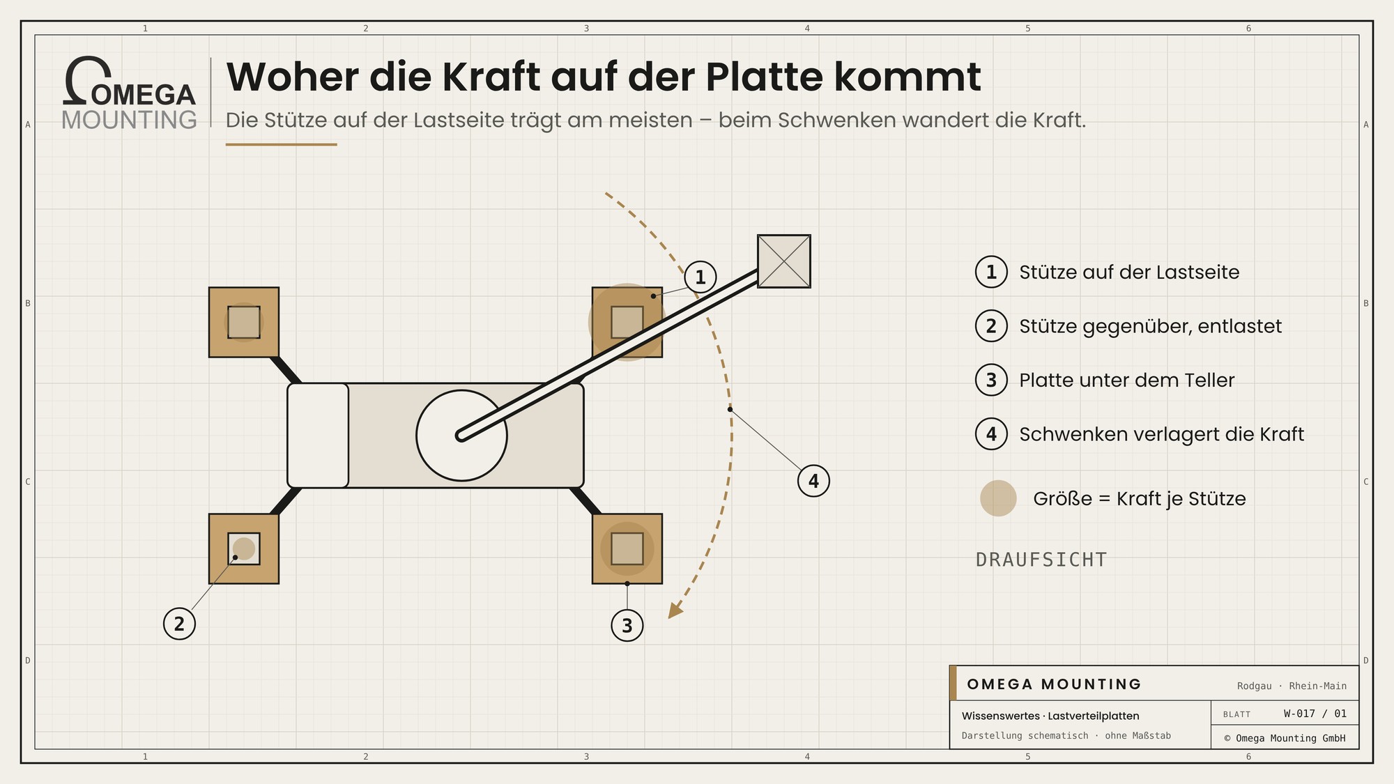
- Mobile crane and mini crane: usually four outriggers; the force per outrigger depends on load, radius and slewing angle.
- MEWP: outrigger feet or wheels; on wheeled platforms, the wheel load on the route counts.
- Machine skates: a few small rollers carry the whole load – high point loads on a small contact area.
- Skidding system: The load rests on a few bearing points; the packing under each point has to take it.
Which load spreading mats are there – and what does each one carry?
Load spreading mats differ mainly in stiffness, self-weight and handling – and therefore in which force they can bring onto which area. The rule of thumb: the higher the outrigger force and the softer the ground, the larger and stiffer the mat has to be.
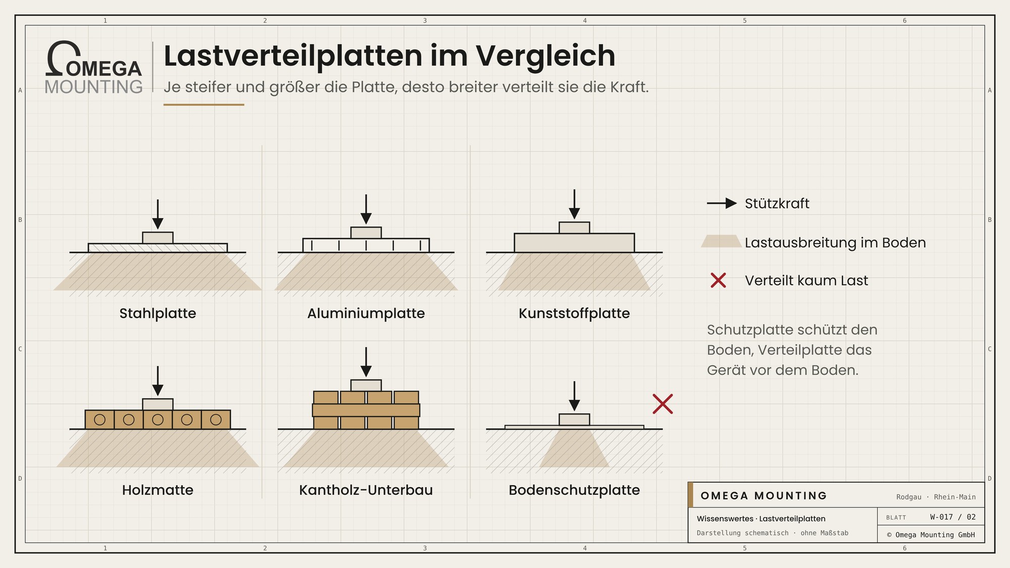
| Mat type | Material | Strength | Limit | Typical use |
|---|---|---|---|---|
| Steel plate | Structural steel, smooth or chequered | Very stiff, spreads high forces even over large areas | Heavy, can only be laid with equipment; slippery when wet | Crane outriggers on soft ground, bridging joints and channels |
| Aluminium outrigger pad | Aluminium, often with handles | Lighter than steel with good stiffness | Notches and dents at the edges weaken it | Outriggers of mobile and mini cranes |
| Plastic pad | Solid polyethylene | Light, slip-resistant, does not absorb water | Less stiff than metal, needs thickness and area; heat deforms it | MEWPs, mini cranes, routes for skates |
| Timber mat (crane mat) | Joined planks or timber baulks | Large area, signals overload by indentation | Heavy, absorbs water, splits and rots over time | Large cranes on unpaved ground |
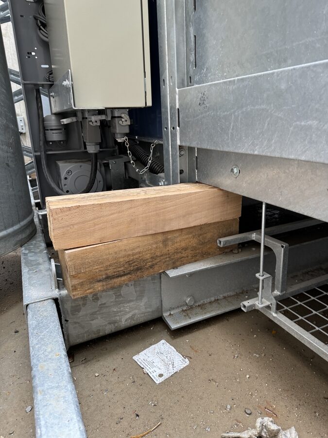
| Timber baulk packing | Stacked timber baulks, laid crosswise | Height and area freely adjustable | Only as good as the stack and its bearing; tips if laid at an angle | Set-down points, temporary support of components, packing under tracks |
| Floor protection board | Thin plastic, often with fleece | Protects surfaces from scratches and dirt | Barely spreads load – not a load spreading mat in the true sense | Routes through finished halls |
The last row is the most important distinction: a protection board protects the floor from the equipment, a load spreading mat protects the equipment from the ground. On sensitive industrial floors you therefore often find both, one on top of the other.
When is the mat no use?
A load spreading mat is no use if there is no load-bearing ground beneath it or if it does not pass the force on evenly. These are the mistakes we see most often:
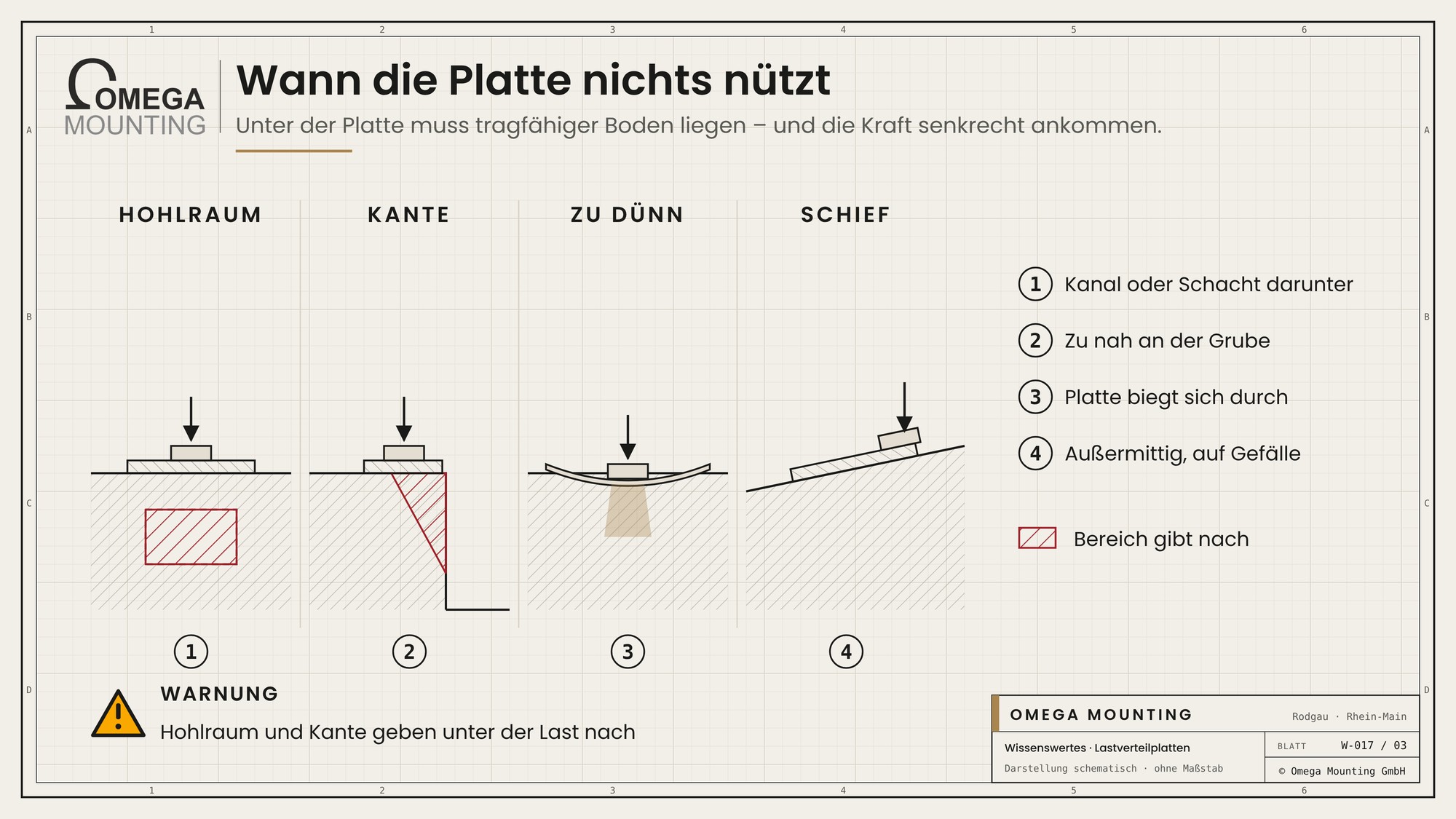
- Mat too small or too thin: The area is not enough on paper, or the mat bends.
- Void underneath: Shafts, ducts, service routes and backfilled trenches lie hidden beneath the surface.
- Edge of a shaft or pit: If the mat sits too close to the edge, the load pushes the edge away.
- Floor without approval: Underground car parks, basement slabs and raised floors look solid but are often not designed for point loads.
- Uneven bearing: Outrigger foot off-centre, mat on a slope or on loose chippings – the force does not go vertically into the ground.
- Stacks without a system: Mats or timbers piled on top of each other that can slip or tip.
What we pay attention to
Our fitters treat the ground under the equipment as part of the lift, not as a given.
- We get the outrigger forces for the specific lift and check them against the approved ground bearing pressure before the crane rigs up.
- We ask for as-built drawings and mark shafts, ducts and services under the crane standing area as a no-go zone.
- We place the mat centrally under the outrigger foot, fully bedded on level ground, and check after set-down whether it has settled.
- On suspended floors and raised floors we move nothing without approval from the structural engineer.
- We lay routes through finished halls with protection boards and fleece and bridge joints and thresholds separately.
- We stack timber baulk packing crosswise and as low as possible – and look at every timber before it goes in.
Where we use it
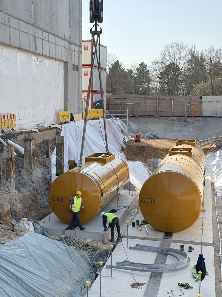
In the Rhine-Main region, the ground has a say in almost every heavy lift. When moving two transformers in on a skid track around 52 tonnes each rested on just a few bearing points. The track was packed, measured and adjusted element by element before the push; the lift management checked the crane position against the ground loading in advance. When five diesel tanks were installed in Raunheim, there were shafts, ducts and basement light wells under the access routes that cannot take point loads from crane outriggers – only after surveying the existing conditions was it clear where the crane could stand. We clarify questions like these as part of Lift & Shift before the first lift.
More technology explained
Technology explained
The track whose bearings must stand on load-bearing packing.
Technology explained
Why with skates the ground is the limit, not the capacity.
Guide
The guide for when you set floor loads and crane standing areas for your project.
Do you have questions about how this works on your site?
Questions about how this works on your site – whether the crane standing area will carry the load, which mats belong under the outriggers or how a route crosses the hall floor? We look at ground, equipment and route together with you. Request a callback – we will get back to you.
Free, no-obligation callback
About the author
Tobias Schott
Managing director of Omega Mounting GmbH, Rodgau · more than 20 years of hands-on experience in installation and maintenance
A trained mechatronics technician, working in maintenance, servicing and industrial installation since 2004 – first alongside his father, and with Omega Mounting since 2012: from overhead conveyors in Frankfurt to the crane system in a new-build hall. He plans and leads lifting operations as an appointed person (AP) in data centers and on industrial sites in the Rhine-Main region, trains and examines operators of cranes, mobile elevating work platforms and telehandlers, and is a qualified occupational safety specialist. On jobs abroad he is known as the “German Troubleshooter” – the person you call when a site gets stuck. He learned what quality means from his father, not from a manual: Made in Germany as a standard for his own work, not a label. That is why quality comes first at Omega Mounting – ahead of speed and price. The Technology explained articles cover the equipment and techniques his team uses every day: what counts on site is in them – what only appears in the brochure is not.
 English
 German