
- Guide – Maintenance
Tapping and drilling threads: tap drill table M2.5 to M30
By Tobias Schott · Reading time approx. 29 minutes · As of: October 2026
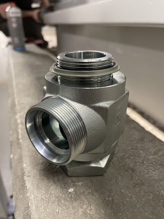
Anyone who wants to cut a thread first needs the right tap drill hole – after that, thread type, pitch, tool and care decide whether the bolt holds.
Anyone who has to cut a thread usually faces a simple question: which drill fits? The answer is in every tap drill table. Even so, many threads go wrong in the workshop and on installation. The tap drill hole is too small and the tap breaks off. Or the thread is crooked and the bolt jams after a few turns.
Then there is a second hurdle: not every thread is metric. Older plants and imported machines contain imperial, Whitworth and pipe threads, and in some places fine or left-hand threads. Anyone who “makes it fit” here destroys components.
This guide gives you the values and the understanding behind them: a tap drill table from M2.5 to M30 with minor diameters and bolt size, a fine thread table, instructions for internal and external threads and help with imperial, Whitworth, left-hand and damaged threads.
We write as an installation and maintenance contractor from Rodgau near Frankfurt. We install, bolt, anchor, build bespoke items in our workshop and repair plants. We are not a turning shop or contract manufacturer – we say so clearly at the relevant points.
Key points at a glance
- In everyday language, tapping a thread means drilling the tap drill hole and then cutting or forming the thread.
- For metric coarse threads the rule of thumb is: tap drill hole equals nominal diameter minus pitch – the exact values are in the tap drill table.
- The tap drill sizes apply to cut threads in steel; for formed threads the hole is larger and comes from the tool manufacturer's table.
- For an external thread, the bolt is turned or chosen slightly thinner than the nominal diameter so that the die does not jam.
- Fine threads have a smaller pitch for the same diameter and are designated with diameter and pitch, for example M10 x 1.25.
- Imperial, Whitworth and pipe threads are not interchangeable with metric threads – even if they look similar.
- Left-hand threads are marked LH and need their own taps and dies.
What is a thread? The terms for thread cutting
A thread is a profiled groove running helically around a cylinder that connects two parts – bolt and nut – with a positive fit and converts rotation into linear movement or a clamping force.
The metric ISO thread is the standard in Germany. DIN 13 sets out the basic dimensions; the minor dimensions of the sizes given here come from ISO 724. Five terms matter for thread cutting.
Nominal diameter, pitch, flank angle
- Nominal diameter (d): the outside diameter of the bolt thread. The number after the M is the nominal diameter in millimetres.
- Pitch (P): the distance from one thread crest to the next, measured lengthwise. With one full turn, the bolt moves exactly one pitch.
- Flank angle: the angle between the two flanks of a thread. On metric threads it is 60°.
- Pitch diameter: the diameter at which thread and groove are equally wide. The flanks of bolt and nut carry the load across it.
- Minor diameter: the smallest diameter of the thread. On the internal thread it is called D1, on the bolt d3.
Internal and external threads
An internal thread sits in a hole, for example in a nut or directly in the component. It is cut with a tap or formed with a thread former. An external thread sits on a bolt, a threaded rod or a shaft. It is cut with a die or rolled in production.
What “tapping a thread” really means
Anyone searching for “drilling a thread” almost always means two work steps. First the tap drill hole is drilled, i.e. a hole at the minor diameter of the internal thread. Then a tap cuts the profile into the wall of the hole. In German the tap is even called a “thread drill” – but it does not drill, it cuts.
Coarse thread, fine thread, tolerance
Every metric size has a coarse thread with a defined pitch. It is designated only with the nominal diameter, for example M10. A fine thread has a smaller pitch and is designated with both values, for example M10 x 1.25.
So that bolts and nuts from different sources fit together, there are tolerance classes to ISO 965. Normal nut threads usually use class 6H, bolt threads 6g. Taps are marked with their tolerance class.
Tap drill table M2.5 to M30: drill, minor diameter and bolt size
The tap drill table gives, for every metric coarse thread from M2.5 to M30, the pitch, the tap drill for cut threads, the minor diameters of nut and bolt and a guide value for the bolt diameter before thread cutting.
The values apply to metric ISO coarse threads, the tap drills to DIN 336 for cut nut threads in tolerance 6H. We cross-checked them against a second, independent table. All dimensions in millimetres.
| Thread | Pitch | Tap drill (DIN 336) | Minor diameter nut D1 | Minor diameter bolt d3 | Bolt Ø before cutting (guide value) |
|---|---|---|---|---|---|
| M2.5 | 0.45 | 2.05 | 2.013 | 1.948 | 2.46 |
| M3 | 0.5 | 2.5 | 2.459 | 2.387 | 2.95 |
| M4 | 0.7 | 3.3 | 3.242 | 3.141 | 3.93 |
| M5 | 0.8 | 4.2 | 4.134 | 4.019 | 4.92 |
| M6 | 1.0 | 5.0 | 4.917 | 4.773 | 5.9 |
| M8 | 1.25 | 6.8 | 6.647 | 6.466 | 7.88 |
| M10 | 1.5 | 8.5 | 8.376 | 8.16 | 9.85 |
| M12 | 1.75 | 10.2 | 10.106 | 9.853 | 11.82 |
| M14 | 2.0 | 12.0 | 11.835 | 11.546 | 13.8 |
| M16 | 2.0 | 14.0 | 13.835 | 13.546 | 15.8 |
| M18 | 2.5 | 15.5 | 15.294 | 14.933 | 17.75 |
| M20 | 2.5 | 17.5 | 17.294 | 16.933 | 19.75 |
| M22 | 2.5 | 19.5 | 19.294 | 18.933 | 21.75 |
| M24 | 3.0 | 21.0 | 20.752 | 20.319 | 23.7 |
| M27 | 3.0 | 24.0 | 23.752 | 23.319 | 26.7 |
| M30 | 3.5 | 26.5 | 26.211 | 25.706 | 29.65 |
Mandatory note. The tap drill sizes apply to cut threads in steel. For formed threads, i.e. produced chiplessly with a thread former, the hole is larger – the value is given in the tool manufacturer's table. Other values may apply in soft or tough materials, in cast iron and in plastic. The drawing and the manufacturer's data remain decisive.
How to read the tap drill table
Look up the thread in the first column and read off the drill in the third column. You drill the tap drill hole for M6 with 5.0 mm. The M8 hole needs a 6.8 mm drill, the M10 hole an 8.5 mm drill. You need the pitch to choose the right tap and the right die.
The rule of thumb: tap drill hole equals diameter minus pitch
For metric coarse threads there is a simple rule of thumb: tap drill hole approximately equals nominal diameter minus pitch. For M10 that means 10 minus 1.5 gives 8.5 – exactly the drill from the table. For M16, 16 minus 2.0 gives 14.0. The formula helps when no table is to hand. For some sizes the standard drill is slightly off the calculated value; then the table applies.
Why the drill is larger than D1

Notice: the tap drill is always slightly larger than the minor diameter of the nut D1. For M6 it is 5.0 against 4.917. That is intentional. D1 is the smallest basic size; the tolerance of the nut thread allows a slightly larger hole. The tap then has to remove less material, cuts more easily and breaks less often. The load capacity of the thread hardly changes, because the flanks carry the load, not the crests.
Minor diameter of the bolt d3: the weakest cross-section
The minor diameter d3 is the narrowest cross-section of the bolt. It is slightly below D1 because the thread root on the bolt is rounded and needs clearance to the nut. For the strength of a bolt, a cross-section between minor and pitch diameter counts – the stress cross-section. For practical purposes: an external thread cut too deep or with scores in the root weakens exactly this area – that is where an overloaded bolt breaks.
The bolt guide value
The last column gives a guide value for the bolt diameter before cutting an external thread. It follows the rule of thumb nominal diameter minus 0.1 × pitch. For M10 that gives 9.85, for M6 5.9. The guide value is a starting value: the die's data and the material may differ. More on this in the chapter on external threads.
Cutting internal threads step by step

You cut an internal thread by hand in six steps: mark out and centre-punch, drill the tap drill hole square, countersink, start the tap square, cut with cutting oil while turning forward and back, and finally remove the chips.
Tools and preparation
You need a drill to the tap drill table, a countersink, a tap or tap set in the right size, a suitable tap wrench and cutting oil. The tap wrench is the holder with two handles into which the square of the tap is clamped. Clamp the workpiece firmly, for example in a machine vice. A part that turns with the tool injures hands and breaks taps.
Marking out and centre-punching
Mark the position of the hole and set a centre punch mark. The punch mark guides the drill point and stops the drill from wandering. For several holes it is best to transfer the hole pattern directly from the mating part.
Drilling the tap drill hole square
Drill the tap drill hole with the drill from the table. Square really means square: this is most reliable on a pillar drill. With a hand drill, a drill stand or drill guide helps. A crooked tap drill hole gives a crooked thread, and no tap corrects that. For larger threads, pre-drill smaller first and then open up to the tap drill size.
Countersinking
Countersink the hole lightly, slightly above the nominal diameter. The chamfer guides the tap when starting. It also prevents the first thread from breaking out or raising a burr on which the bolt later catches.
Starting the tap square
When cutting threads by hand you usually work with a set of taper, intermediate and bottoming taps. The taper tap has the longest lead and a ring on the shank, the intermediate tap two rings, the bottoming tap none. For through holes in easily machinable materials there are single-pass taps that cut the thread completely in one pass.
Start the tap square in the tap wrench. Press lightly in the axial direction until it bites. After the first turns, check with a square from two directions whether it is straight. You can still correct it now – later you cannot.
Cutting with cutting oil, forward and back
Put cutting oil on the tap. Then keep turning clockwise, evenly and with both hands on the tap wrench. After a short distance, turn back a little. This breaks the chips and the tap cuts free again. If the resistance suddenly increases, do not force it: turn back, remove the chips, add oil.
Which lubricant suits depends on the material:
- Mild steel: cutting oil.
- Stainless steel: a cutting oil or cutting paste for difficult-to-machine materials, plus a tap designed for stainless steel.
- Aluminium: a lubricant suitable for aluminium so that nothing sticks to the cutting edges.
- Grey cast iron and brass: often dry, because they form short, crumbly chips.
If in doubt, the tool or lubricant manufacturer's data applies.
Removing chips and checking
Turn the tap out completely and remove the chips. Chips are sharp: use a brush or hook, not your fingers. Do not blow out holes with compressed air without safety glasses and without watching out for people nearby. Check the finished thread with a suitable bolt or a thread plug gauge. The bolt must screw in by hand without jamming.
Through hole or blind hole

A through hole goes through the component, a blind hole ends blind in the material. In a through hole the chips fall out downwards or are pushed forward by the tap. In a blind hole they stay in the hole – and that is the most common cause of broken taps.
For blind holes, therefore:
- Drill deeper than the thread length. The lead of the tap does not cut a full profile, and the drill point leaves a cone. Both need space below the usable thread.
- Mark the depth. Mark the thread length on the tap, for example with adhesive tape.
- Do not run into the bottom. Stop as soon as you feel the bottom. A tap that sits on the bottom or on a pack of chips breaks.
- Remove chips in between. For deep blind holes, turn the tap out completely several times and clear the hole.
- Bottoming tap with a short lead. So that the thread reaches almost to the bottom.
Machine taps, thread formers, combination tools
Machine taps cut the thread in one pass on the drilling machine or in the machining centre. For through holes they have a spiral point that pushes the chips forward. For blind holes they have spiral flutes that carry the chips upwards. On a drilling machine you need a tapping chuck with length compensation and reverse.
A thread former does not cut but presses the profile chiplessly into the wall of the hole. No chips are produced, and the thread becomes stronger through the deformation. In return, the thread former needs a larger tap drill hole, more torque and an easily deformable material. It is generally not suitable for brittle materials such as grey cast iron.
Combined drill taps have a drill point at the front and the cutting edges behind it. They are suitable for thin sheet and profiles where one pass is enough.
Cutting external threads: bolt, die, starting

You cut an external thread with a die: bring the bolt to the right diameter, chamfer the end, start the die in the die stock square with the lead side first and cut with cutting oil while turning forward and back.
The right bolt diameter
The bolt is chosen or turned slightly thinner than the nominal diameter. During thread cutting, material is raised slightly at the flanks. If the bolt were at full nominal size, the thread crests would be too high and tear. The tap drill table gives a guide value from the rule of thumb nominal diameter minus 0.1 × pitch. For an M10 that is 9.85, for an M6 5.9. If a different value is given for the die, that applies.
What happens if the size is wrong?
- Bolt too large: The die jams, the thread crests tear out, the thread becomes rough and stiff. At worst, the die breaks.
- Bolt too small: The thread crests stay flat. The thread carries on only part of the flanks and is weak. The nut wobbles and can strip.
Chamfering the end
Chamfer the bolt end with a file or grinding disc, slightly below the minor diameter. The chamfer guides the die and makes starting straight easier. It also makes it easier to fit the nut later.
Die and die stock
The die is a hardened disc with an internal thread and flutes that cuts the thread. It is clamped in the die stock. The side screws of the holder engage in the recesses on the circumference of the die and hold it firmly. Split dies can be adjusted slightly with an adjusting screw.
The die has a lead side with the first threads ground conically. This side faces the workpiece – usually it is the labelled side. Anyone who starts the die the wrong way round begins with full threads and can hardly get it straight on the bolt.
Starting square and cutting
Clamp the bolt vertically in the vice, with soft jaws so that it does not get pressure marks. Start the die at right angles to the bolt axis. Press evenly until it bites and check the right angle from two directions after the first threads. Cut with cutting oil, alternately forward and slightly back so that the chips break.
Check the thread with a suitable nut or a thread ring gauge. If the nut is too stiff, close the die slightly and cut through a second time.
Where external threads occur in maintenance
In installation and maintenance, cutting external threads mainly occurs in three cases. A threaded rod is shortened and the start must run freely again. A bolt thread is damaged and is re-cut. Or a round bar on a bespoke item needs a thread for fixing. For load-bearing bolts: bought, rolled bolts with a known property class are the better choice. A self-cut thread does not replace a standard bolt.
Pitches: coarse threads and fine threads
A fine thread is a metric thread with a smaller pitch than the coarse thread of the same diameter – it is designated with diameter and pitch, for example M10 x 1.25, and needs a larger tap drill hole.
What the thread pitch does
The thread pitch determines how far a bolt moves with one turn. A small pitch has three consequences. The bolt can be adjusted more finely. The thread is shallower and the core stays thicker. And self-locking is higher, so the bolt is less likely to loosen on its own.
What fine threads are used for
You find fine threads where these properties are needed:
- Thin walls: in pipes, sleeves and thin-walled housings, more threads engage over a short length with a small pitch.
- Fine adjustment: adjusting screws, spindles and adjusting nuts can be set more precisely.
- Higher self-locking: on joints under vibration, for example on axles and shaft nuts.
The downside: fine threads are more sensitive to dirt and damage, and they need their own taps and dies.
Tap drill table for fine threads
The rule of thumb tap drill hole approximately equals diameter minus pitch also applies to fine threads. For M12 x 1.5, 12 minus 1.5 gives exactly 10.5; for M10 x 1 the result is 9.0. The following table gives the tap drills for common fine threads, also for cut threads in steel.
| Fine thread | Tap drill |
|---|---|
| M8 x 1 | 7.0 |
| M10 x 1 | 9.0 |
| M10 x 1.25 | 8.8 |
| M12 x 1.25 | 10.8 |
| M12 x 1.5 | 10.5 |
| M16 x 1.5 | 14.5 |
| M20 x 1.5 | 18.5 |
| M24 x 2 | 22.0 |
The same mandatory note applies as for the main table: values for cut threads in steel; for formed threads and other materials according to the manufacturer's data. The drawing and the manufacturer's data remain decisive.
Identifying threads: calipers and thread gauge
Before you re-cut a thread or order a replacement bolt, you need to know which thread you have. Two tools are usually enough.
With the calipers you measure the outside diameter of the bolt or the minor diameter of the internal thread. On used bolts the outside diameter is usually just under the nominal size. You compare the internal thread with D1 from the table.
The thread gauge, also called a pitch gauge or screw pitch gauge, is a set of thin leaves with tooth profiles. Place the leaves on the thread one after the other. The right leaf sits in the threads without a gap over the whole length. If this leaf shows a pitch in millimetres, the thread is metric. Only the combination of diameter and pitch shows whether it is a coarse or fine thread.
Recognising imperial, Whitworth and pipe threads

Imperial, Whitworth and pipe threads differ from metric threads in their system of measurement, pitch specification and partly the flank angle – they are not interchangeable, even if they seem to fit at first glance.
Imperial threads: UNC and UNF
An imperial thread to the American standard is called UNC for the coarse thread and UNF for the fine thread. As with metric threads, the flank angle is 60°. The difference lies in the system of measurement: the diameter is given in inches. Instead of the pitch in millimetres, the number of threads per inch is given, i.e. how many threads there are over one inch of length.
Because the flank angle is the same, some imperial bolts can be screwed a few turns into a metric thread. Then they jam. Forcing them further destroys both threads.
Whitworth threads: BSW and BSF
The Whitworth thread is a British imperial thread with a flank angle of 55° and rounded crests and roots. BSW is the coarse thread, BSF the fine thread. Here, too, the number of threads per inch is given. You find Whitworth bolts in older machines, on imported plants and in pipework, because pipe threads are based on this profile.
Pipe threads: G, R and BSP
Pipe threads connect pipes, valves and connections. They also have a flank angle of 55°. You need to distinguish two types:
- Pipe thread G is parallel and standardised to DIN EN ISO 228. It does not seal in the thread. Sealing is done by a sealing face, a sealing ring or an O-ring.
- Pipe thread R is tapered, i.e. slightly conical. It seals in the thread, usually with sealing tape, hemp and sealing paste or a thread sealant as specified.
In English-speaking countries both are called BSP. Important: the size designation of a pipe thread is not the outside diameter of the pipe. It is a historical nominal size. A pipe thread whose size sounds like a certain dimension is clearly larger on the calipers. Anyone who orders by the measured diameter orders the wrong part.
NPT: tapered and 60°
NPT is the American tapered pipe thread with a flank angle of 60°. It looks similar to the tapered R thread but is not interchangeable with it. G and NPT do not fit together either. A connection of NPT and G or R will not seal, even if it can be screwed in a few turns.
Never “make it fit”
Mixing up metric and imperial threads is common in maintenance. The rule is simple: a thread is never “made to fit”. Do not re-cut it with a metric tap, do not force it in, do not seal it up with sealant.
Instead, determine diameter, pitch or threads per inch and flank angle. Thread gauges come as a set for metric threads and as a set for imperial threads. If none of the metric leaves fits but an imperial leaf does, you have an imperial thread. Whether it is 55° or 60° is shown by the leaf that sits without a gap. If in doubt, the manufacturer's documentation applies.
Left-hand threads: where they occur and how to cut them
A left-hand thread tightens when turned anticlockwise – it is marked LH and used wherever a right-hand thread would loosen due to the direction of rotation in operation or where mix-ups must be ruled out.
Designation LH
LH stands for “left hand”. The designation follows the thread specification, for example M10 LH. A right-hand thread is normally not marked separately. Some nuts with left-hand threads also have notches or a groove on the corners so that they can be recognised without a trial fit.
Where left-hand threads occur
- Opposing threads: turnbuckles have a right-hand thread on one side and a left-hand thread on the other. One turn of the centre part thus tensions both sides at once.
- Rotating parts: fixings of grinding discs, saw blades and fan wheels on shafts whose direction of rotation would loosen a right-hand thread. The left bicycle pedal is another example.
- Gas cylinders and fittings: connections for flammable gases generally have left-hand threads so that they cannot be confused with connections for other gases.
Cutting left-hand threads
For a left-hand thread you need a left-hand tap or a left-hand die. It does not work with right-hand tools. Cutting is done anticlockwise; otherwise the same applies as for right-hand threads: tap drill hole to the table, start square, cutting oil, forward and back. Left-hand tools are also marked, usually with LH or “links”.
Tightening a left-hand threaded joint requires a torque wrench that releases in the opposite direction. How that works is explained in our guide Using a torque wrench correctly.
Repairing threads: re-cutting, thread insert, broken tap

A damaged thread is re-cut, repaired with a thread insert or – only with approval – drilled out to a larger thread, depending on the damage.
Re-cutting
If a thread is only dirty, gummed up or slightly deformed at the first threads, re-cutting is often enough. Use the bottoming tap in the right size and pitch, or the matching die for a bolt. Turn carefully, without pressure, so that the tool follows the existing threads and does not start a new thread. Clarify first: is it really the thread you think it is?
Thread insert and wire thread insert
If the thread is torn out or stripped, a thread insert helps. It restores the original thread.
- Wire thread insert: a coil of profiled wire. The hole is drilled out with a special drill, cut with a special tap, and the insert is screwed in with an insertion tool. The driving tang is then removed. Wire thread inserts are also common as reinforcement in soft materials such as aluminium.
- Solid thread insert: a sleeve with internal and external threads that cuts itself into the drilled-out hole or is screwed into a pre-cut thread and secured.
Drill, tap and insertion tool belong to the respective system. Dimensions and procedure are in the system's instructions – not in the normal tap drill table.
Oversize only with approval
Drilling out a torn thread to the next size is quickly done. But it changes the design: a different bolt, a different cross-section in the component, a different tightening torque. On load-bearing or safety-relevant joints, the manufacturer or designer therefore decides whether oversize, a thread insert or a new component is right.
A note on tightening: a cut thread in a soft material does not automatically hold the values of a general table. How tightening torques come about and what the guide values apply to is explained in our guide torque table for bolts.
Broken tap: causes

A broken tap is annoying because it is hard and cannot be drilled out. The most common causes:
- Tap drill hole too small. The tap has to remove too much material.
- Started at an angle. It is loaded sideways and breaks.
- Chips not broken. Without turning forward and back, the flutes clog.
- Run into the bottom. In a blind hole it sits on the bottom or on chips.
- No or wrong cutting oil. Friction rises and the cutting edges seize.
- Blunt or wrong tool. For example a tap for mild steel in stainless steel.
Broken tap: procedure
Stop forcing it immediately. If a piece sticks out, it can sometimes be turned back carefully with pliers. For broken pieces in the hole there are tap extractors. They engage in the flutes with narrow fingers and turn the piece out. Remove the chips and add a little oil first.
If the broken piece is stuck, it can be removed by spark erosion. This is done by a specialist company with an EDM machine. For components that cannot be removed, clarify the procedure with the manufacturer or designer. Drilling it out with a normal drill does not work – the drill breaks on the hardened steel, and then there are two tools stuck in the hole.
Typical mistakes when cutting threads
The typical mistakes when cutting threads are a wrong tap drill hole, starting at an angle, no cutting oil, chips not broken, the wrong thread type and a blind hole drilled too shallow.
- Wrong tap drill hole. Too small, and the tap breaks. Too large, and the thread does not hold. Always drill to the tap drill table.
- Former value and cutting value mixed up. A thread former needs a different tap drill hole than a tap.
- Started at an angle. The bolt sits crooked or jams. Check the angle after the first turns.
- No oil. The thread becomes rough, the tap seizes.
- Chips not broken. The flutes clog, the tool breaks.
- Wrong thread type. Imperial instead of metric, fine instead of coarse thread, G instead of NPT. Identify first, then cut.
- Blind hole too shallow. The thread does not reach far enough, the tap runs into the bottom.
- Bolt at nominal size. The die jams, the thread crests tear.
- Oversize without approval. On load-bearing joints this changes the design.
Why these mistakes are so common
Thread cutting is often done on the side under time pressure. Asking three questions before drilling avoids most mistakes: which thread exactly? Which tap drill hole, cut or formed? Through hole or blind hole?
Thread cutting in the Rhine-Main region: how we work
In installation and maintenance in the Rhine-Main region, thread cutting is one of the jobs at the edge of the actual work for us – when a bracket is retrofitted, a damaged thread is made to run freely again or a bespoke item is adapted on site.
Before we drill, we clarify the drawing, thread type and material. In unknown plants we identify the thread before fitting a replacement bolt.
From our workshop in Rodgau, Frankfurt, Offenbach, Hanau, Darmstadt and Aschaffenburg are short trips. The scope of our industrial installation in existing buildings is set out on our service page.
We say beforehand what we do not take on. We are not a turning shop and do not offer contract manufacturing of threaded parts. Re-making shafts, spindles or special bolts belongs with a machining company, eroding a stuck tap with a specialist company. Oversize and thread inserts on load-bearing joints are approved by the manufacturer or designer.
Project examples
Four jobs from our project diary show the work around drilling, bolting and measuring. To be honest up front: none of these reports describes thread cutting. They show where the basics from this guide are found in everyday work.
Nuclear area: drilling the hole pattern for a pillar jib crane
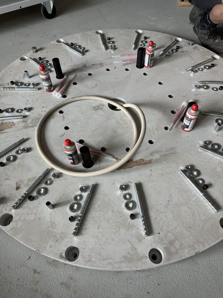
With the workshop fit-out with pillar jib cranes in a nuclear facility, we marked out the base plate and drilled the hole pattern into the concrete floor with direct dust extraction. The drill holes were blown out and brushed out, then came the bonding mortar and anchor rods. Only after the curing time was the column aligned and tightened.
For your thread this means: marking out, drilling and cleaning are not side issues. A clean hole is the foundation – whether for an anchor or for a thread. How machines are anchored is described in our guide Aligning and anchoring a machine.
Test rig in the automotive sector: dowels, bolts, hydraulic fittings
During the Conversion of a test rig with oil sump we adapted the existing hydraulic lines to the new configuration. The sump segments were fixed with dowels and bolts, and all joints were TIG-welded tight. Pressure-tight hydraulic fittings were used on the lines.
For your thread this means: on hydraulics and pipework, the right thread type counts. A fitting that only grips a few turns is not a connection.
Food plant: measure first, then replace
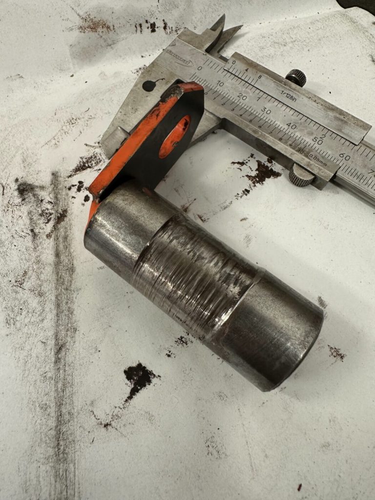
With the Repair of worn pins on an overhead conveyor a pin was pulled and measured with the calipers. Then pin and bearing point were replaced as a pair.
For your thread this means: measuring comes before acting. Anyone who determines diameter and pitch before re-cutting or ordering avoids mixing up thread types.
Production plant near Offenbach: made in Rodgau, adapted on site
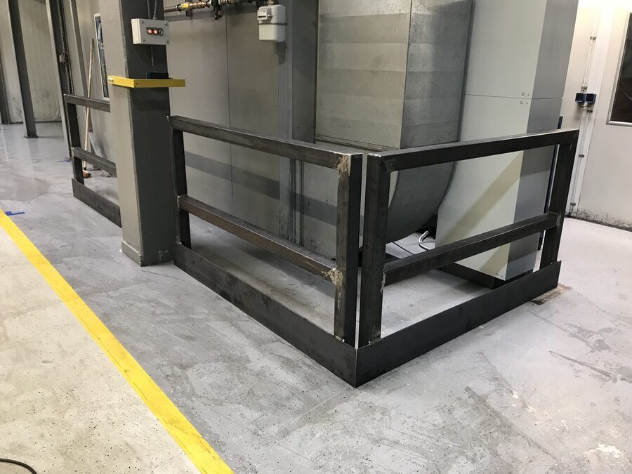
For a bespoke impact guard near Offenbach we cut and welded the structure in our workshop in Rodgau. On site it was adapted to the columns and plant, anchored in the floor with heavy-duty anchors and coated.
For your thread this means: with bespoke items, what fits is decided on site. When a bespoke item is worthwhile is described in our guide Custom metalwork.
Do you have damaged threads or unclear joints on a plant?
Then get in touch with us. Send us photos of the spot, the thread specification from the drawing if available, and a short description. We clarify in advance whether re-cutting, a thread insert or a conversation with the manufacturer is the right way.
What this means for your role
For buyers: Order bolts, threaded rods and thread inserts with the complete thread specification – size, pitch for fine threads, LH for left-hand threads, pipe threads with standard designation. “M10” alone is not enough for fine threads. For imported machines, ask whether metric or imperial threads are fitted.
For designers: Write threads completely on the drawing, for blind holes with usable thread length and drilling depth. Avoid fine threads where they are not necessary – spare parts and tools are less readily available. In soft materials, plan thread inserts or sufficient engagement length from the start.
For project managers and site managers: As project manager, you decide whether drilling and cutting may be done on site and who approves oversize or thread inserts. As site manager, you make sure that chips do not get into machines, hydraulics or bearings, and you ask to see the approval for load-bearing joints.
For maintenance managers: Keep taps, dies and thread gauges ready for the threads in your plants, including imperial and pipe threads where these are fitted. Document repaired threads and fitted thread inserts. A tap drill table at the workbench prevents the most common mistakes.
For occupational safety specialists and HSE coordinators: When drilling and cutting threads, workpiece clamping, safety glasses and the ban on gloves at rotating drilling machines belong in the safety briefing. Chips are removed with a brush or hook. Repairs to safety-relevant joints need an approval.
Tap drill and thread card for the workshop: template on request
The tap drill and thread card is a notice for the workbench and tool trolley. It contains the tap drill table M2.5 to M30 with pitch, tap drill, minor diameters and bolt guide value, the fine thread table from this guide and short rules on tap drill holes, blind holes, cutting oil, external threads, imperial and left-hand threads. Request the card via our contact form – keyword “thread card”.
Why Omega Mounting?
We are based in Rodgau near Frankfurt, can be reached by phone (Mon–Fri 9 am–3 pm) and WhatsApp and have our own workshop for bespoke items. We install, anchor, bolt and repair – on cranes, test rigs, conveyors and production plants. The linked jobs show how we work: mark out, drill, clean, measure, adapt. We say beforehand what belongs with a machining company or the manufacturer. What this means for you: a single point of contact for installation and maintenance – with short distances in the Rhine-Main region.
Conclusion
Thread cutting is not an art, but it is work with little margin. The tap drill hole comes from the tap drill table – for cut threads by the rule of thumb diameter minus pitch, for formed threads according to the manufacturer's data. Start taps and dies square, use cutting oil and break the chips. Before every repair, determine whether you have a metric, fine, imperial, pipe or left-hand thread. If threads on your plant are damaged or joints are unclear, send us photos and the details from the drawing – we will get back to you with an honest assessment.
Further reading: How tight to tighten afterwards: torque table for bolts. How to handle the wrench correctly: Using a torque wrench correctly.
Planning a move-in, installation or maintenance in the Rhine-Main region?
Tell us briefly what you need – we'll come back with an honest assessment.
Free, no-obligation callback
You may also be interested in these guides

About the author
Tobias Schott
Managing director of Omega Mounting GmbH, Rodgau · more than 20 years of hands-on experience in installation and maintenance
A trained mechatronics technician, working in maintenance, servicing and industrial installation since 2004 – first alongside his father, and with Omega Mounting since 2012: from overhead conveyors in Frankfurt to the crane system in a new-build hall. He plans and leads lifting operations as an appointed person (AP) in data centers and on industrial sites in the Rhine-Main region, trains and examines operators of cranes, mobile elevating work platforms and telehandlers, and is a qualified occupational safety specialist. On jobs abroad he is known as the “German Troubleshooter” – the person you call when a site gets stuck. He learned what quality means from his father, not from a manual: Made in Germany as a standard for his own work, not a label. That is why quality comes first at Omega Mounting – ahead of speed and price. He writes these guides from that practice: what works on our sites is in them – what exists only on paper is not.
Frequently asked questions
For a cut metric coarse thread, the tap drill table applies: M6 needs a 5.0 mm drill, M8 a 6.8 mm drill, M10 an 8.5 mm drill. The rule of thumb is nominal diameter minus pitch. The same formula applies to fine threads with the smaller pitch. For formed threads the tap drill hole is larger – the value is given by the tool manufacturer.
The bolt is chosen slightly thinner than the nominal diameter, with a starting value from the rule of thumb nominal diameter minus 0.1 × pitch – for M10 that is 9.85. Chamfer the end, start the die square with the lead side first and cut back and forth with cutting oil. If the die specifies a different size, that applies.
The coarse thread is the standard pitch of a metric size and is designated only with the diameter, for example M10. A fine thread has a smaller pitch and is designated with both values, for example M10 x 1.25. It suits thin walls, fine adjustment and joints that should be harder to loosen, but needs its own tools.
With calipers and a thread gauge. If none of the metric leaves fits without a gap but a leaf from the imperial set does, it is an imperial thread. UNC and UNF have a 60° flank angle, Whitworth and pipe threads 55°. Instead of the pitch in millimetres, the number of threads per inch is given. Never “make” imperial and metric threads fit each other.
LH stands for “left hand” and marks a left-hand thread. The bolt is tightened anticlockwise. You find left-hand threads on turnbuckles, on fixings of rotating parts and on connections for flammable gases. To cut them you need left-hand taps or dies, to tighten them a torque wrench that releases in the opposite direction.
That depends on the material and the task. Thread forming works without chips, the thread becomes stronger and no chips are left in the blind hole. In return it needs a larger tap drill hole, more torque and an easily deformable material. Thread cutting is more universal, also for brittle materials, and easier to do by hand.
Stop forcing it immediately and remove the chips. If a piece sticks out, it can be turned back carefully. For broken pieces in the hole there are tap extractors that engage in the flutes. If the broken piece is stuck, a specialist company removes it by spark erosion. Drilling it out with a normal drill does not work because the tap is hardened.
Re-cutting a dirty thread is usually not critical. Oversize, thread inserts or a new thread on load-bearing or safety-relevant joints, however, change the design. Here the manufacturer or designer decides. Document the repair and have the joint then tightened as specified and, where required, inspected.
Installation and maintenance contractors from the region are the shortest route. From Rodgau we work in Frankfurt, Offenbach, Hanau, Darmstadt and Aschaffenburg. We identify threads, rework joints and install. Re-making threaded parts and eroding are done by machining and specialist companies, approvals by the manufacturers.
With a short enquiry and three details: which plant or assembly, which threads or joints are affected and which documents exist – drawing, manufacturer's data or photos. If needed, we look at the spot on site and send a written assessment. Your contact is Tobias Schott – reachable via our contact form.
 English
 German