
- Technology explained – technology and procedures
Load moment and radius: why a 220 t crane still lifts 28 t at 20 m
By Tobias Schott · 7-minute read · Updated October 2026
Load moment is load times distance – and it decides whether a crane can lift a load safely, not the figure on its rating plate.
You meet load moment in every lift plan, even if the word itself rarely appears there. It hides behind radius, load chart and counterweight. If you understand it, you know why a big crane is ordered for what looks like a small load.
An example from our work in Frankfurt: a 220-tonne-class mobile crane still had about 28 tonnes of capacity at a radius of around 20 metres. So the class rating does not tell you what the crane lifts at every position. Here we explain why, and how to read the figures.
What is load moment?
Load moment is the weight of the load multiplied by its horizontal distance from the crane’s slewing axis or tipping line. It describes how strongly a load tries to tip the crane forward. In German it is called “Lastmoment”.
The distance is called the radius or working radius. It is measured horizontally from the slewing axis of the superstructure to the centre of the hook. The further out the load hangs, the greater the load moment – even if the load weighs the same.
Key facts
- Formula: Load moment = load × radius, following the law of the lever.
- Unit: Tonne-metres (tm) on site, kilonewton-metres (kNm) in structural calculations; 1 tm is roughly 10 kNm.
- Reference point: Radius is measured from the slewing axis; for stability, what counts is the distance to the tipping line, the line through the outriggers on the load side.
- Counterpart: The stabilising moment from the crane’s own weight, counterweight and outrigger base keeps the crane upright.
- Where you find it: On every jib or boom crane – mobile crane, crawler crane, spider crane, tower crane, loader crane.
- Safety device: The rated capacity limiter monitors the moment and stops any movement that would increase it.
- Often confused with: the rated capacity or crane class, which only applies at a short radius.
How is load moment calculated?
Load moment is load times radius – just like a lever, where a small weight far out balances a large weight close to the pivot. A crane is such a lever. The load hangs on one side; the superstructure and counterweight act on the other.
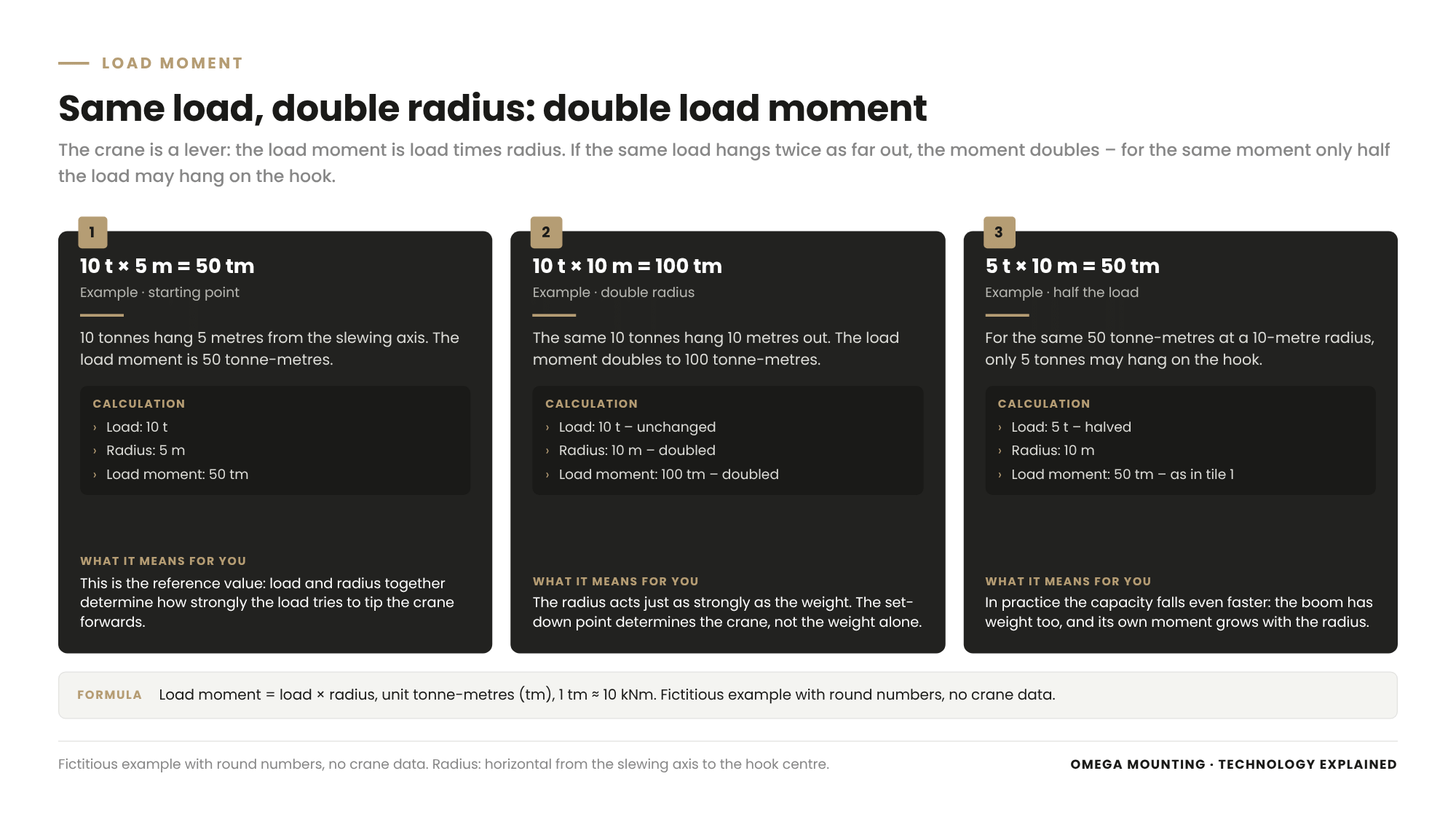
A fictitious example with round numbers, not crane data:
- 10 tonnes at a radius of 5 metres gives 50 tonne-metres.
- The same 10 tonnes at a radius of 10 metres gives 100 tonne-metres – twice as much.
- For 50 tonne-metres at 10 metres, only 5 tonnes may hang on the hook.
So radius has just as much effect as weight. In practice, capacity falls even faster than this calculation suggests, because the boom has its own weight, and its own moment grows as it is lowered or extended.
At a short radius, the strength of boom, rope and hoist usually limits capacity. At a long radius, stability is the limit. Both are built into the load chart.
Radius, counterweight, outrigger base: what determines capacity
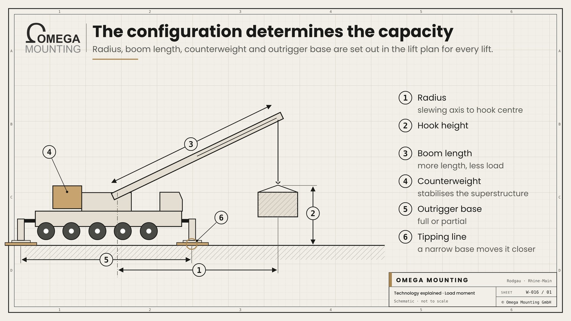
A crane’s capacity depends on its configuration – how boom, counterweight and outriggers are set up for this particular lift. These values are in the lift plan:
| Parameter | What it means | What it means for planning |
|---|---|---|
| Radius | Horizontal distance from the slewing axis to the centre of the hook | The set-down point decides the crane, not the weight alone |
| Hook height | Height of the hook above ground | Tall buildings and long rigging need longer booms |
| Boom length | Extended length of the main boom, possibly with a fly jib | More length gives reach but costs capacity |
| Counterweight | Ballast on the superstructure, fitted on site | More counterweight means more stabilising moment, but also more transport loads and rigging time |
| Outrigger base | Spread of the outriggers, fully or partly extended | A narrow base brings the tipping line closer, and capacity drops |
| Slewing range | Direction of the load relative to the carrier, e.g. over the rear or the side | Some charts only apply to certain zones |
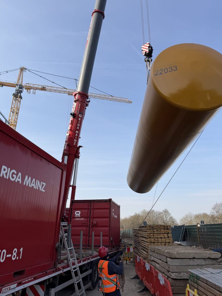
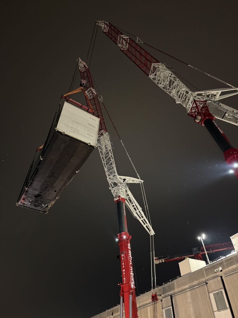
Our lift in Raunheim shows how large this can get: the crane worked there with a 52-metre main boom and a radius of up to 44 metres. Empty, each tank weighed around 16 tonnes. It was not the weight that made the lift big, but the reach across the excavation.
How do you read a crane load chart?
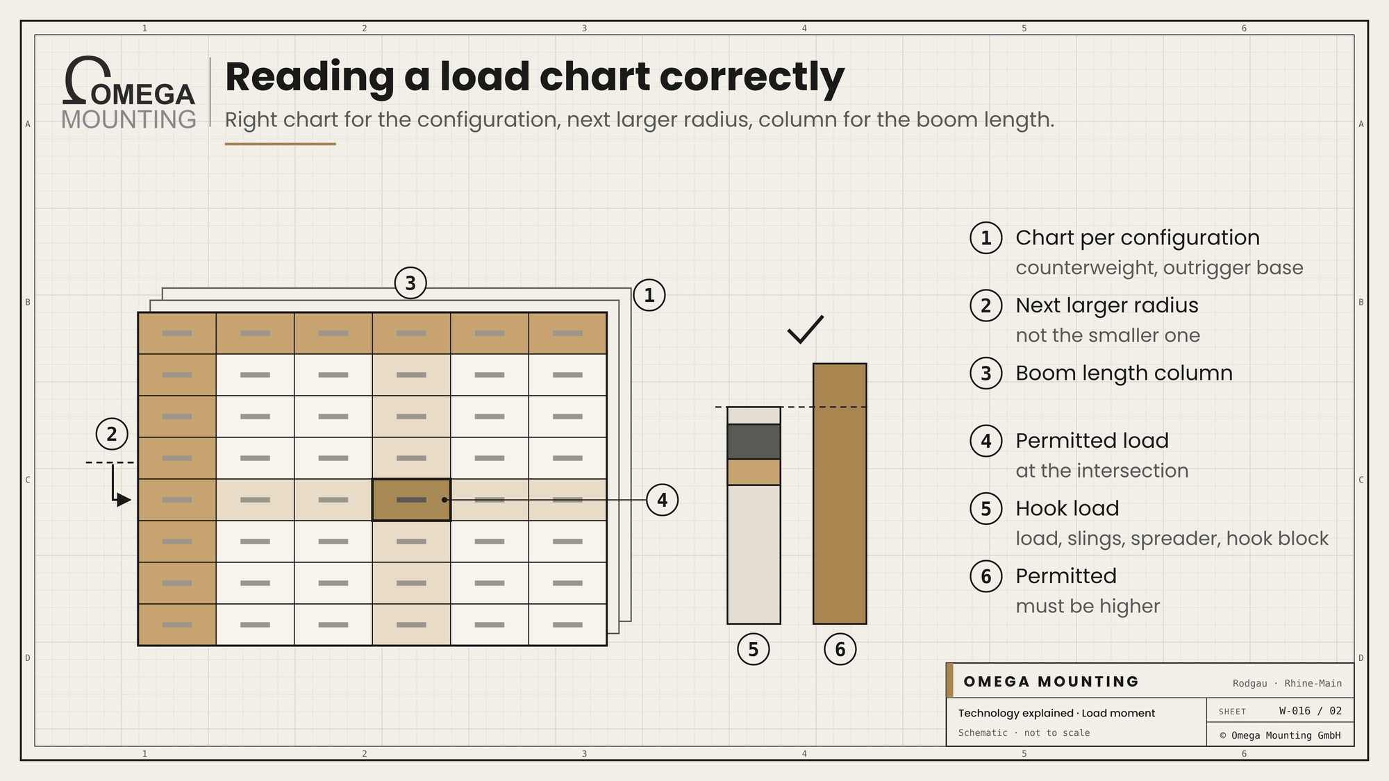
You read a load chart by radius in the row and boom length in the column – where they meet is the permitted load for exactly that configuration. Each combination of counterweight and outrigger base has its own chart. If you open the wrong chart, you read the wrong value.
In principle, the steps are:
- Fix the configuration: counterweight, outrigger base, slewing range.
- Choose the matching chart.
- Find the row with the next larger radius, not the next smaller one.
- Read the permitted load in the boom length column.
- Compare this value with the hook load.
The hook load is more than the weight of the load. It includes slings, shackles and below-the-hook devices – see our article Spreader beam; depending on the chart, it also includes the hook block. In Raunheim, each tank hung from a rigging set of round slings and shackles as tall as a small house. That weight and that height belong in the calculation too.
Rated capacity limiter, wind and swinging loads: what protects the crane
The rated capacity limiter (RCL, also called load moment indicator) protects the crane from overload by constantly comparing the actual load moment with the permitted value and cutting out dangerous movements. It measures load, boom angle and boom length and knows the configuration that has been set. For mobile cranes, EN 13000 requires such a limiter.
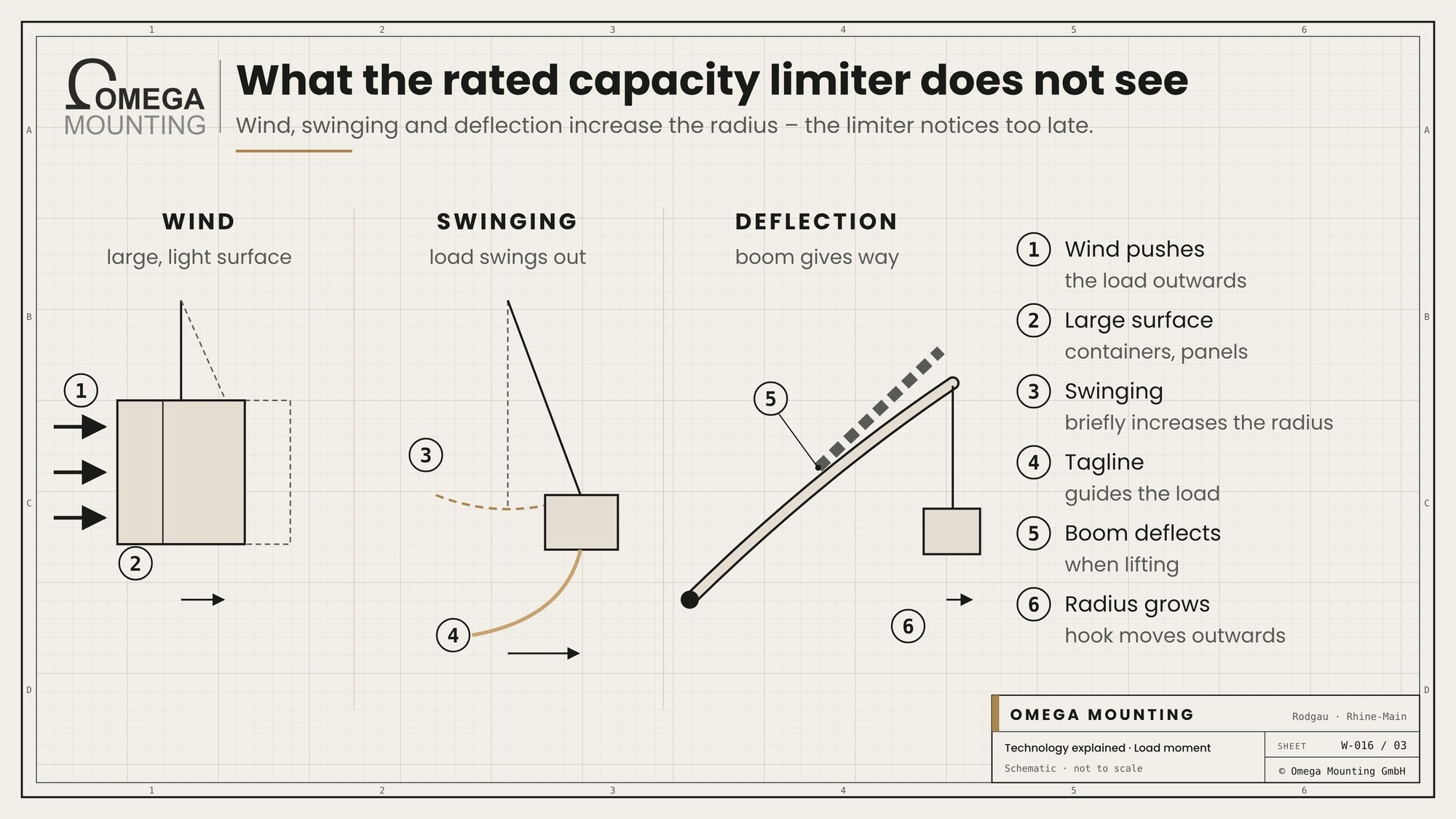
But the limiter only knows what it is told. If the counterweight is entered wrongly, it calculates with the wrong values. It does not see the following, or sees them too late:
- Wind. It presses on the load and the boom and pushes the load outwards. Large, light surfaces such as containers or panels are particularly sensitive.
- Swinging. A swinging load increases the radius for a moment and creates additional forces. That is why we control loads with tag lines.
- Deflection. A telescopic boom bends slightly under load. The radius becomes larger as the load is lifted than it was unloaded.
- Side loading. A load pulled at an angle loads the boom sideways – it is not built for that.
- Tandem lift. When a load hangs on two cranes, each limiter only sees its own share. The load distribution must be in the lift plan beforehand.
In Germany, cranes are subject to DGUV Regulation 52, with inspection before first use and periodic inspection. Clarify with your inspector which duties follow for you as the client – we do not give legal advice. UK readers: LOLER 1998 requires every lift to be properly planned (regulation 8) and cranes to be thoroughly examined at least every 12 months; BS 7121-1 covers lift planning by an appointed person.
What we pay attention to
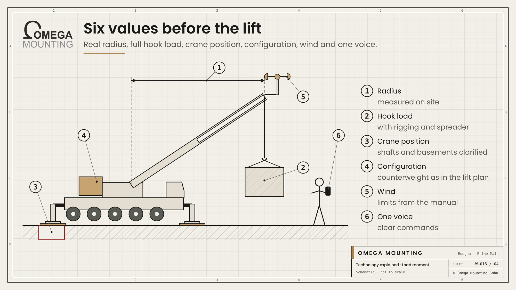
The crane calculates the load moment, but the assumptions behind it come from planning. This is what we check before every lift:
- The real radius. We measure the set-down point on site, not just on the drawing. One metre more can mean a different row in the chart.
- The full hook load. Weight from the manufacturer or a weighbridge ticket, plus rigging, spreader beam and attachments. If the centre of gravity is unclear, we recalculate the sling geometry.
- The crane standing area. The load moment goes into the ground through the outriggers. Shafts, ducts and basement slabs often cannot take point loads like these.
- The configuration. Counterweight, outrigger base and boom must be set up as the lift plan specifies – and entered in the limiter accordingly.
- Wind and weather. We check the limits in the operating manual and would rather postpone a lift than run it in gusts.
- One voice. The crane is driven by the crane hire company’s operator. Our appointed person (AP) plans the lift, a lift supervisor appointed by the AP runs it on site, and our crew slings the load and gives the signals.
Where we use it
We factor in load moment and radius on every crane lift, whether in a data center or an industrial hall. For the move-in of generators and load banks in Frankfurt counterweight, outriggers and configuration were set up exactly to the lift plan: 71 tonnes of counterweight, 30 metres of boom, around 20 metres of radius. When setting five diesel tanks in Raunheim we were the appointed person for lifting operations, in the middle of a residential area with little room for the crane. For what we do in lifting and moving heavy plant, see our page Lift and Shift.
More technology explained
Technology explained
the equipment for which load moment is calculated.
Technology explained
even a small crane has a radius, outriggers and a load chart.
Guide
the guide to choosing a crane.
Do you have questions about how this works on your site?
Questions about how a long-radius lift would run on your site – from the crane standing area to the hook load? We plan the lift with you and the crane hire company. The quickest way is a callback – briefly describe your load, building and date.
Free, no-obligation callback
About the author
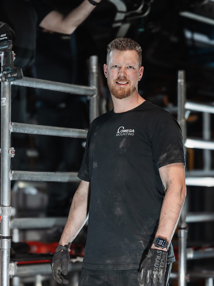
Tobias Schott
Managing director of Omega Mounting GmbH, Rodgau · more than 20 years of hands-on experience in installation and maintenance
A trained mechatronics technician, working in maintenance, servicing and industrial installation since 2004 – first alongside his father, and with Omega Mounting since 2012: from overhead conveyors in Frankfurt to the crane system in a new-build hall. He plans and leads lifting operations as an appointed person (AP) in data centers and on industrial sites in the Rhine-Main region, trains and examines operators of cranes, mobile elevating work platforms and telehandlers, and is a qualified occupational safety specialist. On jobs abroad he is known as the “German Troubleshooter” – the person you call when a site gets stuck. He learned what quality means from his father, not from a manual: Made in Germany as a standard for his own work, not a label. That is why quality comes first at Omega Mounting – ahead of speed and price. The Technology explained articles cover the equipment and techniques his team uses every day: what counts on site is in them – what only appears in the brochure is not.
Frequently asked questions
Yes. On the lifts we plan, our appointed person (AP) prepares the lift plan with radius, hook load and crane configuration, and a lift supervisor appointed by the AP runs the lift on site. The crane itself is driven by the crane hire company’s operator. When we set five diesel tanks in Raunheim, for example, we were the appointed person for lifting operations.
In our RAMS and lift plans we use no more than 80 % of the load chart for the configuration in use. The full hook load including rigging and spreader beam, and the real radius measured on site, go into that check. Where the crane manufacturer and the GC set different wind limits, the lower one applies. Before the main lift we make a trial lift of about 10 cm.