
- Guide – Lift & Shift
Transformer Replacement: Moving In, Skidding and Positioning in Existing Buildings
By Tobias Schott · Reading time approx. 24 minutes · Last updated: October 2026
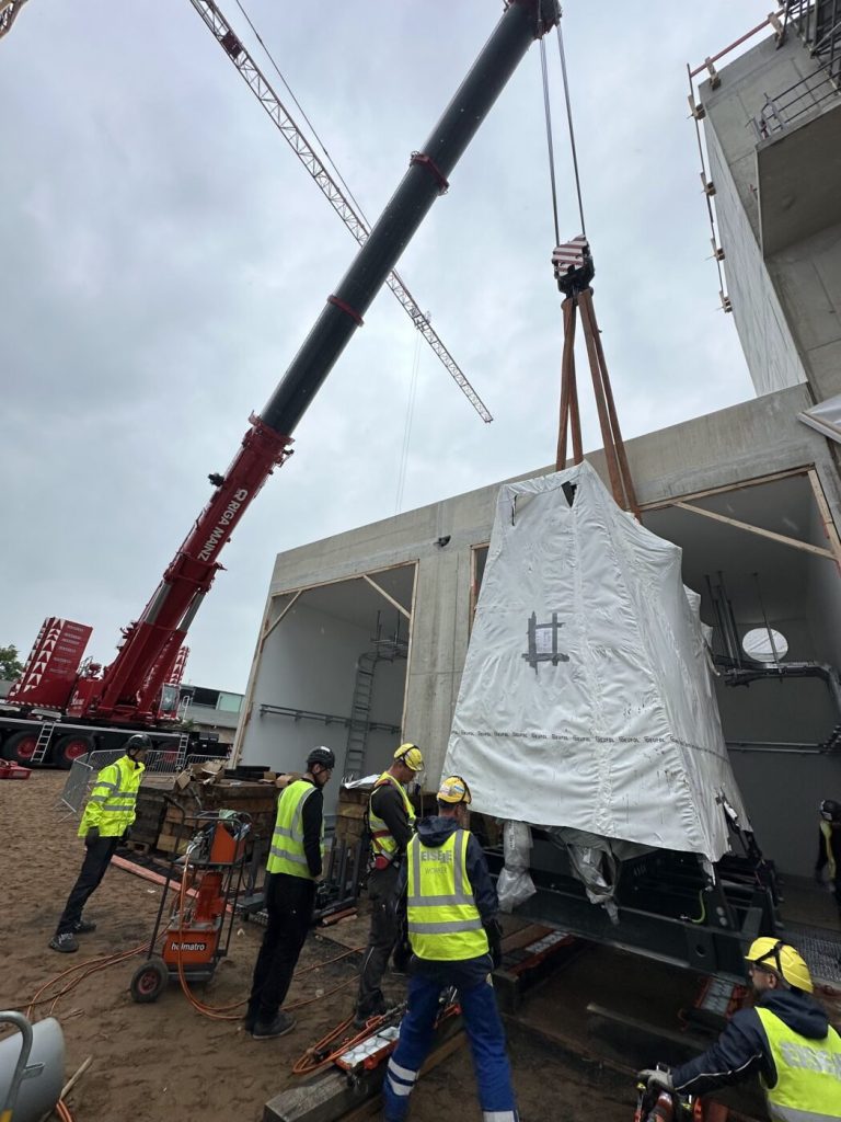
Replacing a transformer in an existing building means planning two projects: the electrical one with the electrical contractor and the network operator – and the mechanical one, which decides whether the new unit is actually standing in the cell on the outage date.
The transformer is the component nobody thinks about as long as it runs. Then the electrical contractor reports a finding, the capacity is no longer sufficient for the new plant, or the substation is being rebuilt. Now it has to be replaced – and with the new unit comes the question of how it gets into a building that has grown around the old transformer for decades. Anyone planning a transformer replacement realises at this point: the connection is sorted, the route is not.
The gate is narrower than the new transformer, behind the gate there is a sloping ramp, the cell has a pit, and the floor slab above it cannot take point loads. The network operator has set the outage date, and the chain of dates behind it leaves no day in reserve. Anyone who only then starts thinking about the skidding system, crane set-up area and floor loads will have to move the date.
This guide expands on our core page on installation in data centers for the heaviest energy component found there and in every industrial substation. It describes the mechanical part of a transformer replacement: planning, routes for moving in, sequence and typical obstacles. Electrical work, medium voltage, isolation, earthing and commissioning remain with the electrical contractor and the network operator – we only describe their steps as far as the installation work depends on them. You will not find weights, prices or time promises here.
Key points at a glance
- A transformer replacement consists of an electrical and a mechanical project: isolation, connection, testing and commissioning by the electrical contractor and the network operator; transport route, moving in, skidding, setting down and removal by the installation contractor.
- Weight, centre of gravity and dimensions are stated on the rating plate and in the manufacturer’s drawing – they are the basis of every lifting and transport plan.
- The route decides the method: mobile crane as far as the opening, then machine skates – or a skidding system if the load is too heavy for skates.
- Floor loads, slabs, pits and ramps are checked by the structural engineer; without their approval, no transformer enters the building.
- The old unit leaves the cell along the same route in reverse – often without any documentation.
- The network operator’s outage date is the fixed point; the installation work is planned backwards from it, with a fallback plan.
- Handover is documented: position, alignment, fixing, photos and report – as the basis for the connection and the next replacement.
What is a transformer replacement from an installation perspective?
From an installation perspective, a transformer replacement is the exchange of a transformer in an existing transformer cell or substation: the old unit is removed, the new unit is brought in along an existing route, aligned and fixed in the cell and then handed over to the electrical contractor for connection.
The term needs to be distinguished in two directions. A new installation in a new building has open wall sections, free space and no outage date. Dismantling without replacement ends with an empty room – more on this in our guide to industrial dismantling and plant removal. Replacement in an existing building lies in between: the building is finished, the route is fixed, and the supply next door usually keeps running.
Mechanically, this includes:
- Transport route from the low-loader to the cell, including access, crane set-up area and bottlenecks.
- Moving in by crane, ramp, opening or shaft.
- Skidding inside the building on machine skates or a skidding system.
- Setting down and alignment on rails, foundation or set-down points.
- Removal of the old unit along the same route in reverse.
It does not include isolation, earthing, medium-voltage connection, testing and commissioning. What we offer around transformers is shown on our service page Moving in and installing transformers.
When is a transformer replaced?
A transformer is replaced when it has reached the end of its service life, when the plant behind it needs more capacity, when damage has been found or when the substation is being rebuilt – and in all four cases the trigger is electrical, the consequence mechanical.
| Reason | Identified by | Mechanical consequence |
|---|---|---|
| End of service life. | Electrical contractor during testing or condition assessment. | New unit often has different dimensions and a different weight. |
| Capacity increase. | Designers and operator when the plant is extended. | Larger unit in the same cell – route and floor are checked again. |
| Damage. | Electrical contractor after a fault or finding. | Time pressure; temporary supply arranged by the electrical contractor, moving in within the time window. |
| Substation rebuild. | Designers, network operator, operator. | Several units, modified cells, interface with construction and electrical work. |
What matters for the installation work is the consequence: the new unit is rarely identical to the old one. A cast-resin transformer – a dry-type transformer without oil, usually in a protective enclosure with fans – can replace an oil-immersed unit, or vice versa. Weight, centre of gravity, lifting points and skate spacing then change. If you know this early, you plan the route for the new unit, not for the old one.
Transformer replacement: who does what?
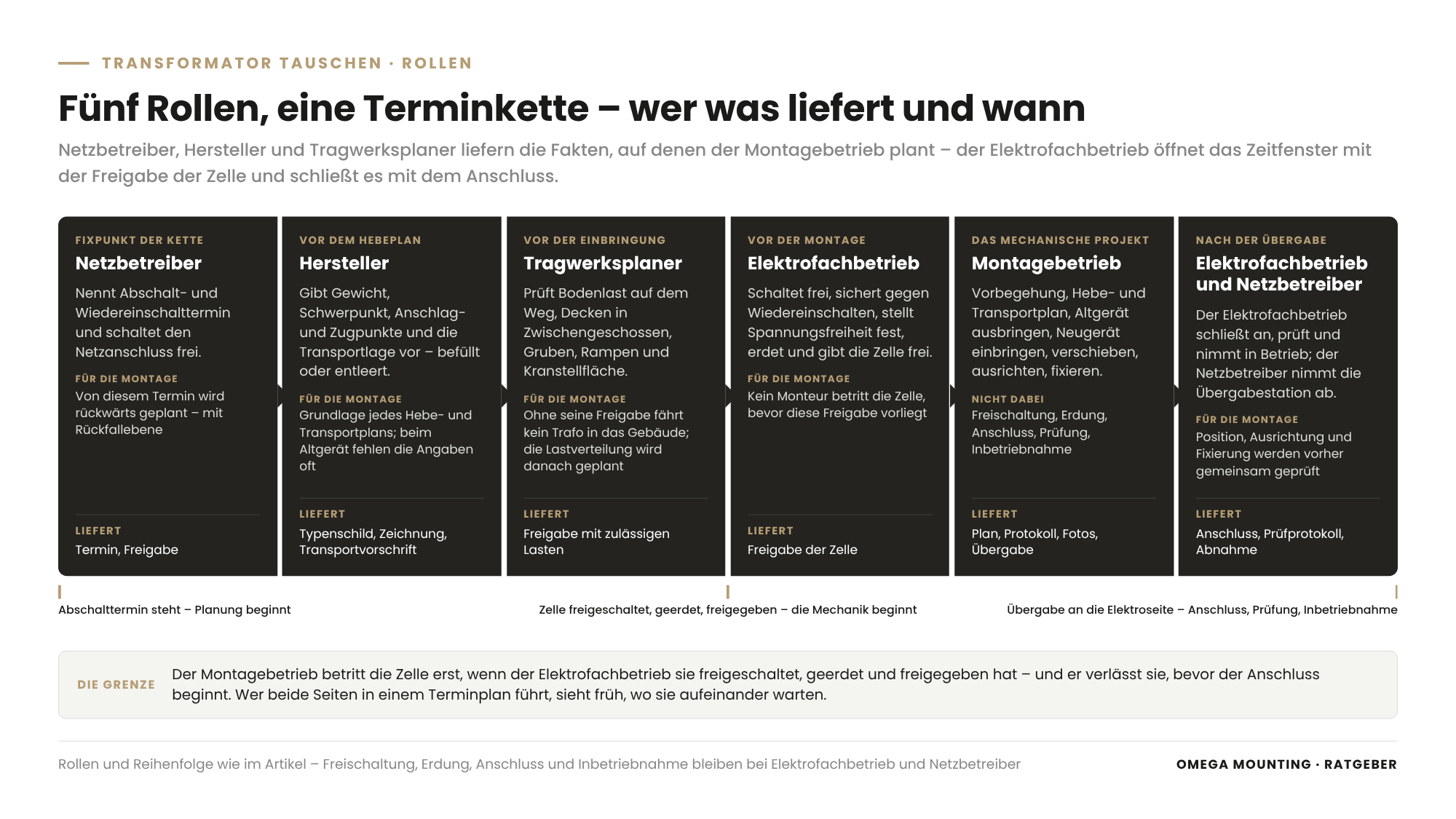
In a transformer replacement, five roles work along one chain of dates: the network operator sets the outage date; the electrical contractor isolates, earths, connects and commissions; the structural engineer approves floors and slabs; the manufacturer supplies weight, centre of gravity and transport requirements – and the installation contractor brings the unit into the cell on this foundation of facts.
| Role | Task in the transformer replacement | Delivers |
|---|---|---|
| Network operator (DNO). | Outage and reconnection dates, isolation of the grid connection, acceptance of the transfer substation. | Date, release, acceptance. |
| Electrical contractor. | Isolate, secure against reconnection, verify absence of voltage, earth, connect, test, commission. | Release of the cell for installation work, connection, test report. |
| Structural engineer. | Floor loads along the route, slabs in intermediate floors, pits, ramps, crane set-up area. | Approval with permissible loads. |
| Manufacturer. | Weight, centre of gravity, lifting and pulling points, transport position, whether the unit travels filled or drained. | Rating plate, drawing, transport instructions. |
| Installation contractor. | Preliminary site visit, lifting and transport plan, removal, moving in, skidding, alignment, fixing, documentation. | Plan, report, photos, handover. |
The boundary is sharp: the installation contractor only enters the cell once the electrical contractor has isolated, earthed and released it, and leaves before connection begins. The mechanical project lies in between. If you manage both sides in one schedule, you see early on where they would be waiting for each other. As an installation partner, we often work on behalf of a crane and heavy-haulage company, a general contractor or an electrical contractor; what this means for procurement is described in our guide to commissioning industrial installation.
What needs to be planned mechanically before a transformer replacement?
Before a transformer replacement, seven parameters are clarified: weight and centre of gravity, dimensions and door openings, the access route, floor loads and slabs, the pit or oil containment bund as a structural constraint, the time window with redundancy, and access and crane set-up area.
Weight and centre of gravity
The weight is on the rating plate, the centre of gravity in the manufacturer’s drawing. Both apply to the transport condition: an oil-immersed transformer with a conservator tank has a high centre of gravity and is moved filled or partially drained as specified by the manufacturer. For the old unit, this information is often missing; it is then researched from the manufacturer’s data for that type, and the plan includes a margin. How round slings, chain slings and spreader beams relate to the centre of gravity is explained in our guide to lifting accessories for heavy loads.
Dimensions, door openings and bottlenecks
The new transformer has to pass through every opening along the route: gate, door, shaft, cell door. The clear door width is measured with the unit on its transport equipment – skates or a track add height. Then come curve radii, swept paths and the clear height under cable trays. Attachments such as fans, protective enclosures and terminal covers are removed according to the manufacturer’s instructions if they block the way.
The access route
The access route is the path from the low-loader to the final position – with every ramp, every slope and every pit. It is walked, surveyed and drawn up; the method follows from it.
Floor loads and slabs
A transformer on four skates creates four point loads; a skidding system places line loads on its supports. Critical areas are intermediate floors, basement slabs, ducts and shafts under the route, and the edge of the transformer pit. The permissible loads come in writing from the structural engineer; the installation contractor then plans load distribution via plates and packing. The basics are covered in our guide to planning moving in and floor loads.
Pit and oil containment bund
Below an oil-immersed transformer there is an oil containment bund or transformer pit that collects the oil in the event of damage – often covered with grating, a gravel bed or rails. For the installation work it is a structural constraint: the load must not stand on the grating, the track is spanned across the pit, and the set-down points are prepared. Whether the bund is adequate for the new unit is checked by the designer.
Time window and redundancy
If the plant is fed by several transformers, one can be taken out of service while the others carry the load. If it depends on a single one, a temporary supply or a shutdown is needed. Both are organised by the electrical contractor together with the operator; the installation work is planned into that window, with a fallback plan. The ground rules are set out in our guide to Maintenance during live operations.
Access and crane set-up area
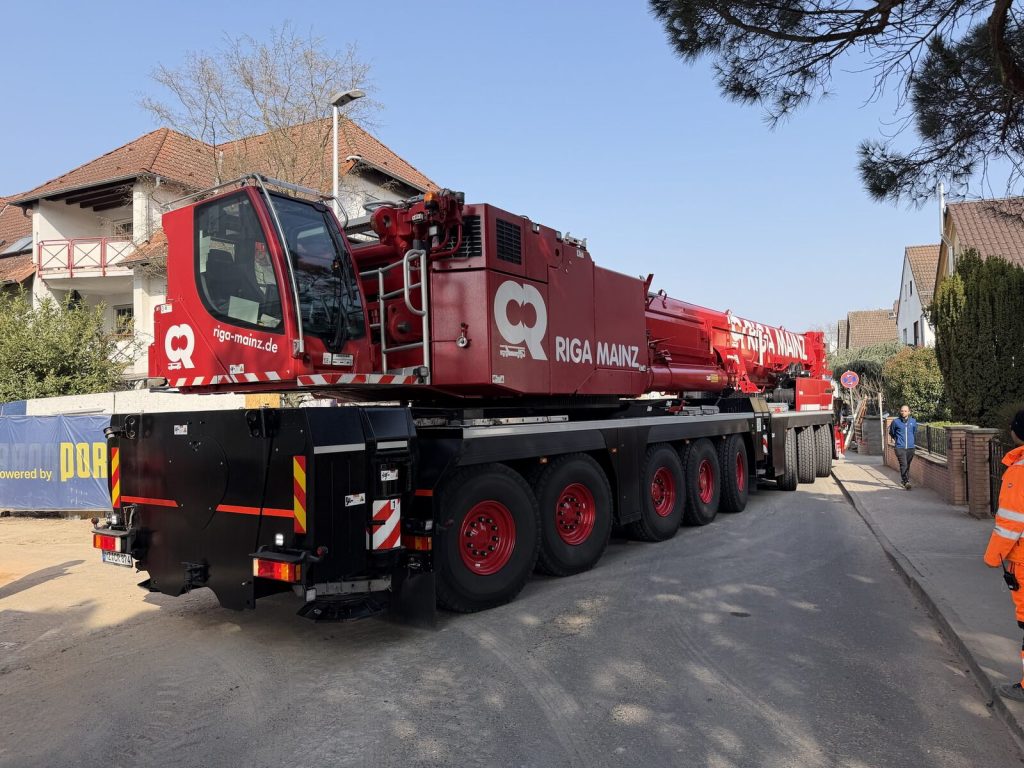
The low-loader has to reach the building, and the mobile crane needs somewhere to stand. In established industrial estates and residential areas, this is the first hurdle: narrow streets, trees, gates, utility lines and shafts under the set-up area. The crane set-up area is defined and approved together with the crane company, and the access route is checked with a swept-path analysis. What needs to be secured on the low-loader is described in our guide to Load securing for heavy goods.
How does a transformer get into an existing building?
A transformer gets into an existing building by one of four routes: directly by mobile crane onto the foundation, via a ramp or opening on machine skates, via a skidding system if it is too heavy for skates or the crane cannot reach the cell, or by a combination of crane, track and hydraulic jacking blocks.
| Route | When it fits | What is prepared for it |
|---|---|---|
| Mobile crane direct. | Cell accessible from outside, foundation within the slewing range. | Crane set-up area, lift plan, lifting points as specified by the manufacturer. |
| Machine skates. | Load-bearing, level floor, curves, weight within the skates’ range. | Floor protection, load spreading plates, pulling points, forklift or winch as drive. |
| Skidding system. | Load too heavy for skates, straight route, crane only reaches the opening, pit in the way. | Laying and levelling the track, packing, hydraulics, set-down points. |
| Combination. | Crane up to the opening, track into the cell, hydraulic jacking blocks for setting down. | Transfer point between crane and track, lift plan for both sections. |
Mobile crane up to the opening
The mobile crane lifts the transformer off the low-loader – and often nothing more. In a finished building it reaches as far as the opening or onto a ramp; a lift from above fails because of the closed roof. Which type of crane suits which set-up area is explained in our article on mobile cranes and crawler cranes.
Machine skates inside the building
Machine skates – often called tank skates on site – carry the transformer on short pairs of rollers and allow changes of direction. They need a load-bearing, level floor without thresholds and a drive that pulls or pushes. Where their limits lie is covered in our article on machine skates and heavy-duty skates.
Skidding system for the heaviest load
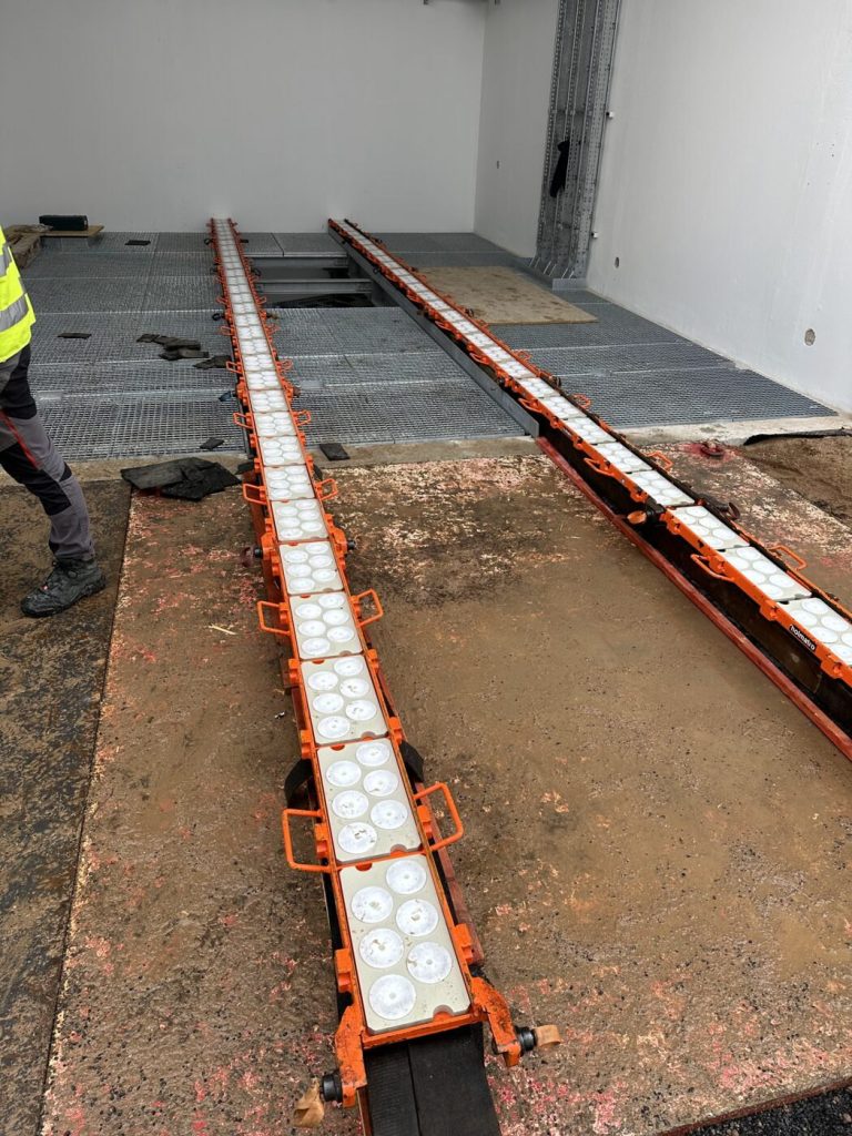
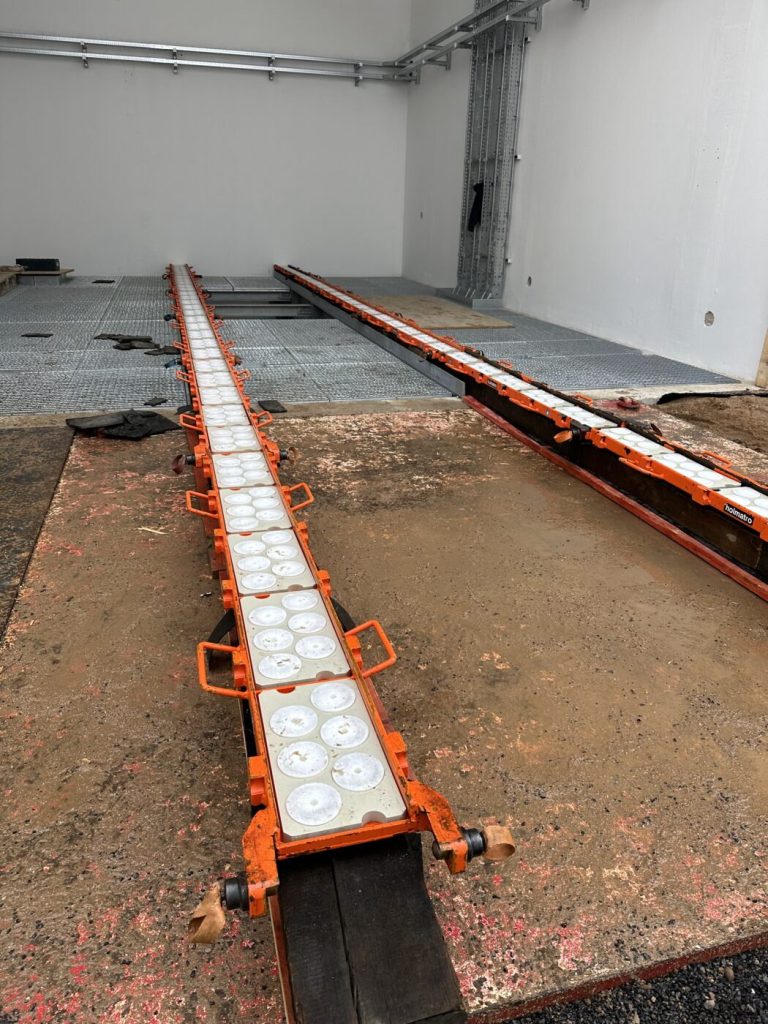
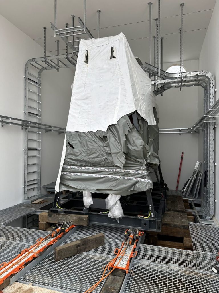
A skidding system is a steel rail or slide track laid on the floor, along which hydraulic cylinders push the load horizontally into place stroke by stroke. It is chosen when the load is too heavy for skates, the route is straight or a pit has to be bridged. After each stroke the load stands still while pressure, position and alignment are checked. At the destination, hydraulic jacking blocks lift the unit, the rail sections are pulled out and the transformer is set down on its set-down points. Design, components and limits are explained in our article on the skidding system.
Mini crane and shaft
For smaller transformers in basements, a spider crane, gantry crane or chain hoist on lifting beams can be used – electrically powered where combustion engines are prohibited inside the building. When a spider crane is the better choice is explained in our guide on spider crane or mobile crane for moving in.
How does a transformer replacement work mechanically?
Mechanically, a transformer replacement follows eight steps: preliminary site visit, lifting and transport plan, isolation and release of the cell by the electrical contractor, removal of the old unit, moving in the new unit, alignment and fixing, handover to the electrical contractor, and documentation.
- Preliminary site visit. Route, openings, floors, pit, access and crane set-up area are surveyed and photographed; rating plate and drawing of both the old and the new unit are available.
- Lifting and transport plan. For every lift and skidding section, weight, centre of gravity, lifting points, lifting accessories, lifting equipment, load path, exclusion zones and responsible persons are defined. An appointed person for lifting operations releases every lift – how this is organised is shown in our guide to the appointed person for lifting operations.
- Isolation and release. The electrical contractor isolates, secures against reconnection, verifies the absence of voltage, earths and releases the cell. Only now does the mechanical work begin; how releases are documented is explained in our guide to lockout and tagout in maintenance.
- Removing the old unit. Remove attachments according to the manufacturer’s instructions, raise the unit, place it on skates or the track, travel the route in reverse, hand it over to the crane or low-loader. If oil has to be drained, the specialist contractor does it.
- Moving in the new unit. By crane up to the opening, then on skates or the track into the cell, stroke by stroke, with a check after every lift.
- Alignment and fixing. The unit is set down on rails, foundation or set-down points, aligned in line and level and secured against shifting as specified by the manufacturer; removed attachments are refitted.
- Handover to the electrical contractor. Position, alignment and fixing are checked jointly; from here on, connection, testing and commissioning belong to the electrical side.
- Documentation. Photos of the initial condition, route, skidding and final position, lift plan, alignment report, punch list – as part of the plant file and the basis for the next replacement.
What generally applies to trial runs and the handover of a plant is set out in our guide to commissioning and handover – for a transformer, this part is handled exclusively by the electrical side.
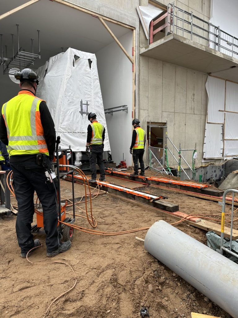
Typical obstacles when you replace a transformer
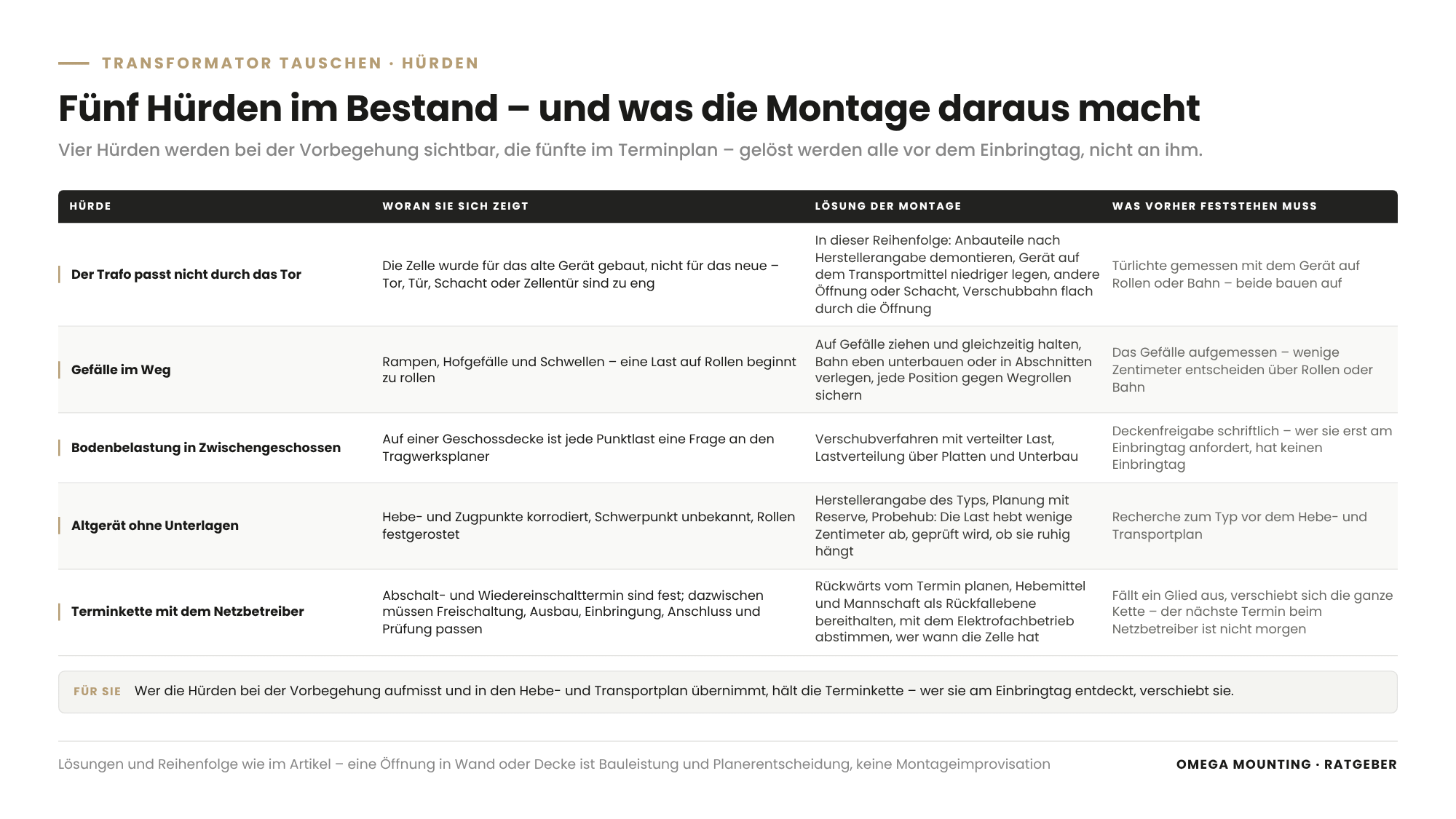
The typical obstacles in a transformer replacement in an existing building are a gate that is too narrow, a slope along the route, a slab without reserve for point loads, an old unit without documentation and a chain of dates with the network operator that has no slack.
The transformer does not fit through the gate
The cell was built for the old unit, not the new one. Solutions in this order: remove attachments according to the manufacturer’s instructions, lower the unit on its transport equipment, use a different access opening or a shaft – or a skidding system that pushes the load flat through an opening that would be too small for a crane lift. Creating an opening in a wall or slab is construction work and a designer’s decision, not installation improvisation.
Slope along the route
Ramps, sloping yards and thresholds are dangerous for a load on skates because it starts to roll. On a slope, the load is pulled and held back at the same time, the track is packed level or laid in sections, and every position is secured against rolling away. What looks like a few centimetres on paper decides on site between skates and a track.
Floor loads on intermediate floors
Transformer cells are not always at ground level. On a floor slab, every point load is a question for the structural engineer – and often the reason why a skidding method with distributed load is chosen. Anyone who only requests the slab approval on installation day will not have an installation day.
Old unit without documentation
Lifting and pulling points are corroded, the centre of gravity is unknown, rollers are rusted solid. Here we work with the manufacturer’s data for the type, with a margin and with a trial lift in which the load is raised only a few centimetres to check that it hangs steadily.
Chain of dates with the network operator
The outage date is fixed, and so is reconnection. In between, isolation, removal, moving in, connection and testing all have to fit. The installation team plans backwards from the date, keeps lifting equipment and crew on standby as a fallback, and agrees with the electrical contractor who has the cell when. If one link fails, the whole chain shifts – and the network operator’s next available date is not tomorrow.
Safety during transformer replacement: isolation, earthing, load area
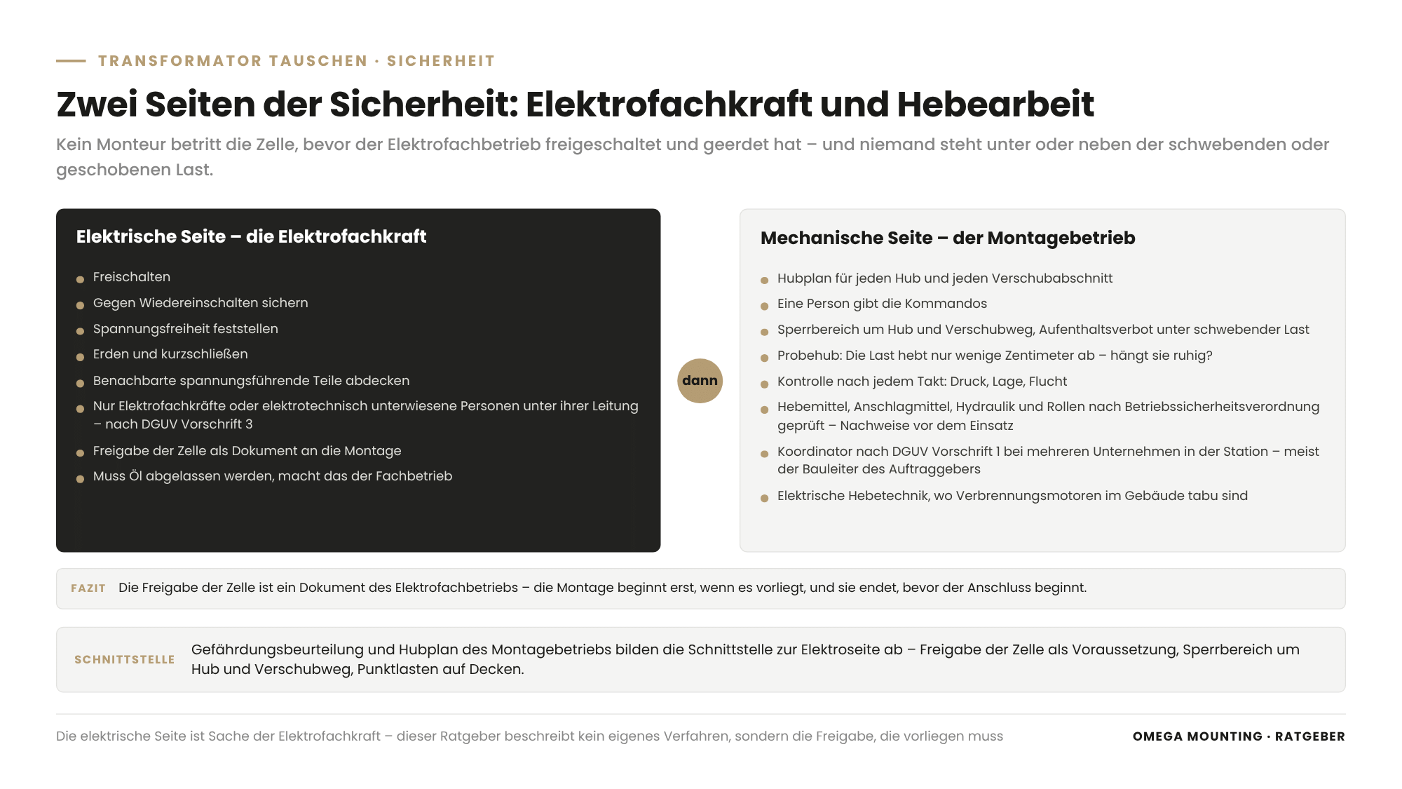
Safety during transformer replacement means: no fitter enters the cell before the electrical contractor has isolated and earthed it, nobody stands under or next to the suspended or skidded load, and every piece of lifting equipment has been inspected.
The electrical side is the responsibility of the qualified electrician. Under DGUV Regulation 3 (German accident insurance regulation on electrical installations and equipment), work on electrical installations may only be carried out by qualified electricians or by electrically instructed persons under their supervision. The five safety rules of electrical engineering – isolate, secure against reconnection, verify absence of voltage, earth and short-circuit, cover adjacent live parts – are carried out and documented by the qualified electrician. For you this means: the release of the cell is a document issued by the electrical contractor, and installation work only begins once it is available.
The mechanical side follows the rules of any lifting operation: lift plan, one person gives the signals, exclusion zone around the lift and skidding route, no one under a suspended load, trial lift, check after every stroke. Lifting equipment, lifting accessories, hydraulics and skates are inspected at regular intervals under the BetrSichV (German Industrial Safety Ordinance); the records are available before use. If several companies work in the substation, DGUV Regulation 1 requires a coordinator – in a transformer replacement usually the client’s site manager. How the risk assessment and lift plan work together is described in our guide to Lift & Shift installation.
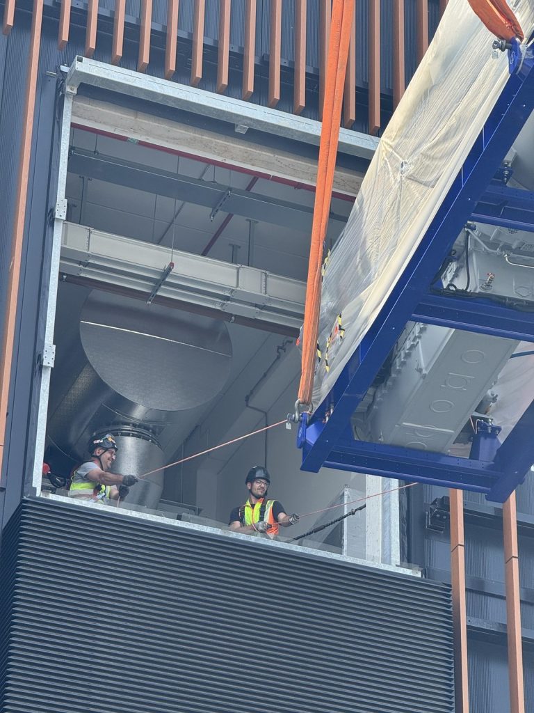
Transformer replacement in a data center: what is different?
In a data center, a transformer replacement is an intervention in a redundant supply during live operation – with change request, maintenance window, access list, escort, a ban on combustion engines inside the building and documentation that records every lift.
Data centers are built so that one unit is allowed to fail: transformers, standby power systems and UPS systems are installed in multiples. The replacement takes place while the neighbouring cells keep running – with less reserve than usual. The operator’s maintenance window and change request determine when the cell may be taken out of service. Between mid-November and early January, many operators block planned interventions altogether – more on this in our guide to change freeze in maintenance.
Mechanically, three things change. First, the lifting equipment: inside the building, spider cranes, lifting devices and pulling equipment run on electric power, and the mobile crane stays outside. Second, the route: transformer cells are often located on upper floors, the route runs through façade openings or heavy-duty lifts, and every slab load is approved. Third, the lead time: access list, induction and lift plan approval take days to weeks. The same applies to the standby power system next to it; how it is maintained is explained in our guide to the maintenance of standby generators.
Transformer replacement in the Rhine-Main region: how we do it
In the Rhine-Main region we move transformers and other energy components into data centers in Frankfurt and Raunheim, into industrial substations between Offenbach, Hanau and Darmstadt and for energy suppliers – with short distances from Rodgau.
The region has two particular features. First, the density of data centers in Frankfurt, Raunheim, Offenbach and Hanau – each has transformer cells that will be replaced at some point. Second, the location: many buildings stand in established industrial estates or residential areas, with access roads never designed for a low-loader carrying a transformer. That is why the site visit is the first step, not the drawing. If you are tendering the mechanical work, you will find the items in our guide to the scope of works for installation and moving in.
How we do it in practice
Four jobs from our project diary show how we bring heavy energy components into existing buildings.
Frankfurt: two transformers on the skidding system
With the moving-in of two 52-tonne transformers into a data center near Frankfurt there was one key constraint: the building had already been closed, so a lift from above was out of the question. The mobile crane set each transformer directly from the low-loader onto a hydraulic skidding system that ran from the building entrance into the transformer cell. The outer track had been packed and levelled beforehand, and stacked timber baulks lay in the pit as set-down points. Then the unit moved towards the cell lift by lift; after every hydraulic stroke the load stood still while pressure and position were checked – a good hour of pure skidding time per unit. In the final position, hydraulic jacking blocks raised the transformer, the rail sections were removed and the unit was set down in the correct position. Two mechanics and a lifting supervisor needed one long working day for this, as a subcontractor to a crane and heavy-haulage company – over 100 tonnes in total.
For your transformer replacement this means: the crane brings the load up to the opening, the track does the rest – and the set-down points in the pit are prepared before the low-loader arrives.
Rhine-Main: standby power systems on upper floors
With the moving-in of standby generators into a data center in the Frankfurt area came a question of height: the generator rooms were on the first and second floors, with a lifting height of around 16 metres. The heaviest single generator weighed just over 20 tonnes, the heaviest containerised solution 54 tonnes – it was placed in a tandem lift with two mobile cranes of the 650-tonne class, with one person giving the signals. Inside the closed building, the units continued on machine skates because combustion engines were prohibited indoors. Commissioning was carried out by the manufacturer.
For your transformer replacement this means: upper floor, façade opening and skates inside the building are the same task for a transformer as for a generator – just with a different centre of gravity.
Raunheim: five diesel tanks through a residential street
During the setting of five diesel tanks for a data center in Raunheim our role was that of the appointed person for lifting operations: lift plan, crane positions, inspection of the lifting points, supervision and release of every lift. Each tank held 100 cubic metres, weighed around 16 tonnes empty and was over 16 metres long. The access road was a residential street, gates had to be removed for the crane, and under the set-up area lay shafts and ducts that could not take point loads from the outriggers. Three working days, each tank delivered individually as a heavy transport.
For your transformer replacement this means: access, crane set-up area and whatever lies beneath it are clarified before the lifting and transport plan.
Frankfurt: generators and load banks in one day
With the moving-in of generators and load banks into a data center in Frankfurt came five heavy transports, arriving in sequence and unloaded straight away. A mobile crane of the 220-tonne class with 71 tonnes of counterweight lifted the container modules over a multi-storey steel structure and set them down to the centimetre. Nine people did this in one extended shift; the lift plans had been approved in the operator’s system beforehand and the crane inspection had been documented.
For your transformer replacement this means: the chain of delivery, lift and release holds within a single day – provided the plan has been approved beforehand. The same applies to removal, as the Spider crane from the basement of a data center in Raunheim shows: site survey, lift plan, electric operation, angled slinging to cope with a dimensional deviation of two centimetres.
Do you have a transformer replacement coming up where the route is the open question?
Then get in touch with us. Send us the rating plate and drawing of the new unit, photos of the access, opening and cell, and the outage date set by the network operator. During a site visit in the Rhine-Main region, we walk the route with you and tell you honestly whether crane, skates or track will work.
What this means for your role
For buyers: Award the mechanical part of the transformer replacement with a clear scope – preliminary site visit, lifting and transport plan, removal, moving in, alignment, documentation – and state what the client provides: isolation, crane set-up area, slab approval, disposal. A quotation that describes the route for moving in is comparable; one that simply says “move in transformer” as a lump sum is not.
For designers: Provide the rating plate and drawing of the new unit, the route with openings and slopes, the permissible loads for floors, slabs and pit edge, and the details of the oil containment bund. Whoever checks the cell for the new unit should check the route to it at the same time – every transformer will have to come out again in a few decades.
For project managers and site managers: As a project manager, you manage the chain of dates between network operator, electrical contractor, crane and installation team backwards from the outage date, with a fallback plan. As a site manager, you coordinate the trades in the substation, record the release of the cell in writing, release the lift and accept position, fixing and documentation before the electrical contractor connects the unit.
For maintenance managers: For you, the transformer replacement starts with the electrical contractor’s finding and ends with a plant file that will still be useful at the next replacement: rating plate, drawing, access route, slab approval, photos of the final position. Keep the access route clear of later installations.
For facility managers and operators: You specify the maintenance window, change request, access list, permissible floor loads and the contact person who issues releases during the job. Define a fallback plan in case the window is not long enough, and request the handover documentation in a format that fits your building file.
For safety officers and HSE coordinators: Check whether the installation contractor’s risk assessment and lift plan cover the interface with the electrical side: release of the cell as a precondition, exclusion zone around the lift and skidding route, electric lifting equipment inside the building, point loads on slabs. Align induction and briefing so that no fitter hears two different sets of rules.
Transformer moving-in checklist: template on request
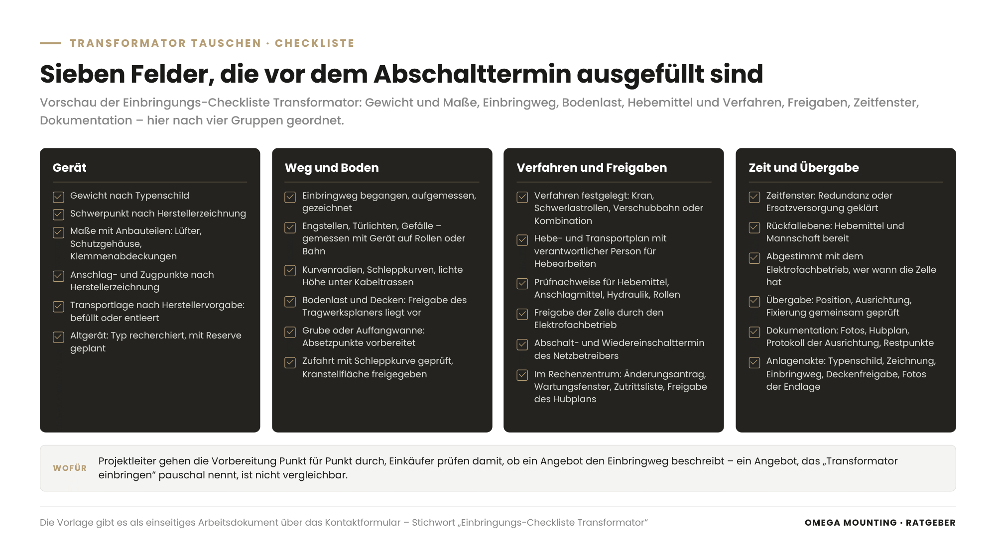
The transformer moving-in checklist summarises on one page what has to be clarified before the outage date: weight, centre of gravity and dimensions; the access route with bottlenecks, slopes and clear door widths; floor loads and slabs with the structural engineer’s approval; lifting equipment and method; the releases from the electrical contractor and the network operator; the time window with a fallback plan; documentation and handover. It helps project managers work through the preparation point by point, and buyers check that a quotation is complete. Request the checklist using our Contact form – keyword “Transformer moving-in checklist”.
Why Omega Mounting?
We are based in Rodgau near Frankfurt, right in the middle of the Rhine-Main data center market, and we bring heavy energy components into existing buildings: two transformers totalling over 100 tonnes on the skidding system in Frankfurt, standby power systems onto upper floors, diesel tanks through a residential street in Raunheim. We take on the transport route, moving in, skidding, setting down, alignment and removal – and deliberately not what belongs to the electrical contractor. Our workshop in Rodgau fabricates packing and load spreading plates when the standard solution does not fit; via our 24-hour hotline you can reach us when a replacement falls into a night-time or weekend window. For you this means: a single point of contact for the mechanical part of the transformer replacement, lifting technology and installation from a single source – and short distances in the Rhine-Main region.
Conclusion
Replacing a transformer means bringing two projects together: the electrical one with the electrical contractor and the network operator, and the mechanical one that brings the unit along a given route into an existing cell. Weight and centre of gravity come from the rating plate, floor loads from the structural engineer, the outage date from the network operator – and the access route decides whether crane, machine skates or skidding system move the unit. Clarify the seven planning parameters before the outage date and you keep the chain of dates; discover them on installation day and it shifts. If you need a transformer replaced and the route is the open question, send us the rating plate, photos of the access and cell, and the outage date – we will get back to you with a site visit date and an honest assessment.
Planning maintenance, moving in or installation in the Rhine-Main region?
Tell us briefly what it is about – we will come back to you with an honest assessment.
100% free and without obligation
You may also be interested in these guides

About the author
Tobias Schott
Managing director of Omega Mounting GmbH, Rodgau · more than 20 years of hands-on experience in installation and maintenance
A trained mechatronics technician, at home in maintenance, servicing and industrial installation since 2004 – first at his father's side, since 2012 with Omega Mounting: from the overhead conveyor in Frankfurt to the crane system in a new-build hall. Plans and leads lifting operations as appointed person in data centers and on industrial sites in the Rhine-Main region, is an instructor and examiner for cranes, mobile elevating work platforms and telehandlers, and a safety officer. On jobs abroad he is known as the “German Troubleshooter” – the one you call when things get stuck on site. He learned what quality means not from a manual but from his father: Made in Germany as a standard for his own work, not as a label. That is why it comes first at Omega Mounting – before speed and before price. He writes these guides from that practice: what works on our sites is in them – what only exists in the standard is not.
Frequently asked questions
The electrical side – isolation, earthing, medium-voltage connection, testing and commissioning – may only be carried out by an electrical contractor, in coordination with the network operator. The mechanical side – removal, moving in, skidding, setting down and alignment – is handled by an installation contractor with a lifting and transport plan and an appointed person for lifting operations. Floors and slabs are approved by the structural engineer; weight and transport requirements come from the manufacturer.
By one of four routes: directly by mobile crane if the cell is accessible from outside; on machine skates if the floor can take the load; via a skidding system if the unit is too heavy for skates or the crane only reaches the opening; or by a combination of crane, track and hydraulic jacking blocks. Which route fits depends on weight, openings, floor and distance – established during a site visit.
The weight is stated on the rating plate and in the manufacturer’s drawing, and it applies to the transport condition specified by the manufacturer – for oil-immersed units, filled or partially drained. General figures do not help, because design, rating and cooling determine the weight. For an old unit without a legible rating plate, the manufacturer’s data for the type is researched and the plan includes a margin.
That depends on the redundancy, not on the installation work alone. If the plant is fed by several transformers, it keeps running on the others and the replacement takes place within the maintenance window. If it depends on a single unit, the electrical contractor arranges a temporary supply or plans a shutdown covering isolation, removal, moving in, connection and testing. Any figure without a site visit and coordination with the network operator would be a guess.
The mechanical effort depends on the access route, the method, crane and set-up area, the slab approvals, the condition of the old unit and the time window – daytime, night or weekend. On top of this come the electrical contractor’s work and the unit itself. A figure can only be given after a site visit.
The replacement takes place in a redundant supply during live operation: with change request, maintenance window, access list, escort and approval of the lift plan by the operator. Inside the building, the lifting equipment runs on electric power, the route often leads to upper floors, and every slab load is approved. The lead time for access and approvals is longer than in an industrial hall.
Yes. Whether data center, production plant or energy supplier – the division of work between electrical contractor and installation contractor, the seven planning parameters and the four routes for moving in are the same. In industrial plants, access and documentation are usually simpler; on the other hand, substations are older, access roads are narrower and documentation on the old unit is less often available.
The cell is isolated by the electrical contractor, secured against reconnection, verified free of voltage and earthed before any fitter enters it. For the mechanical work, the lift plan, exclusion zone, ban on standing under suspended loads, trial lift and inspected lifting equipment apply. This guide does not replace legal advice; it tells you which releases must be in place.
Because a transformer replacement depends on the site visit and on short distances on installation day. From Rodgau, data centers in Frankfurt, Raunheim and Offenbach and substations in Hanau, Darmstadt and Aschaffenburg can be reached quickly – for the site visit, the job itself and the part from the workshop that turns out to be missing on installation day. Add to that local knowledge of access and crane set-up areas in densely built-up locations.
With a short enquiry containing three items: rating plate and drawing of the new unit, photos of the access, opening and cell, and the outage date or maintenance window. We review the documents, propose a site visit and send you a written assessment of the access route, method, lead time and documentation. Your contact is Tobias Schott – reachable via our Contact form, keyword “transformer replacement”.
 English
 German